闪耀光栅
前言
在现代光学系统中,衍射光学元件凭借其结构紧凑、功能灵活等优势,被广泛应用于光谱分辨、波长选择、光束整形等领域。其中,闪耀光栅是一种经过专门优化的衍射结构,其通过在光栅表面设计特定的闪耀角,能够将入射光能量高效地集中到某一特定衍射级次,从而显著提升效率并抑制不希望的衍射能量分布。本案例使用 FDTD 仿真了一个闪耀光栅并分析它在不同衍射级次下的能量分布情况。

仿真设置
结构设置
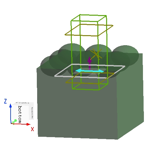
本案例中使用的闪耀光栅由一个低折射率基底( )和厚度为 的高折射率涂层( )构成。光栅的闪耀角为 ,周期为 。在软件中可以直接调用内置的 Blaze grating 结构组,快速完成光栅的几何建模。

求解器设置
仿真采用 2D FDTD 仿真,由于结构具有周期性,因此在 方向的仿真区域宽度设置为 ,与光栅周期保持一致,并在该方向上使用 Bloch 边界条件,从而只需仿真单个周期即可得到无限周期光栅的结果。
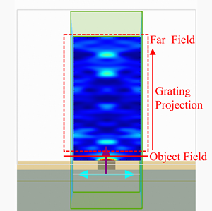
为了保证结果准确,仿真区域内应完整包含结构中变化剧烈的部分,以保证电磁场在边界附近得到充分解析。

光源设置
如下图所示,平面波光源在不同频率下的面内波矢量保持恒定,因此在宽带仿真中,实际的入射角会随频率变化而发生偏移。
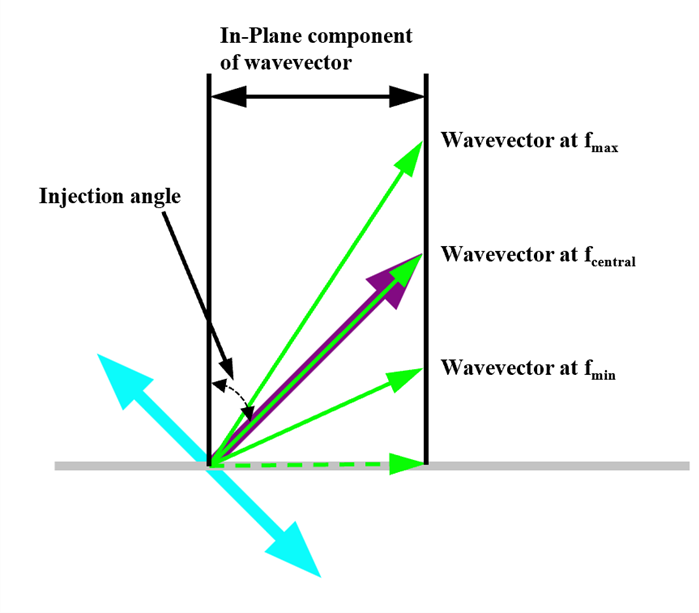
为避免该问题,本案例中使用单频点平面波光源,以 角倾斜入射。通过对光源的频率进行参数扫描,可以在保证入射角不变的条件下,获得光栅在不同频率下的衍射特性。
仿真结果
运行附件中的 blaze_grating.msf 脚本计算光栅在固定波长下的反射和透射的光栅阶数,以及每个衍射阶的强度。下图为 波长下反射与透射中各个衍射级的强度。


可以看到反射和透射中能量主要都集中在单一的衍射阶(闪耀级次),其他衍射级的能量占比较小。这表明该光栅能够有效的将入射光能量定向分布至目标衍射方向,符合衍射光栅“能量集中于闪耀级次”的典型特性。
参数分析
附件工程中包含一个设置好的参数扫描,可以对光源的入射波长从 到 之间的范围进行扫描。扫描完成后可获得各波长下反射至所有衍射阶的总能量,如下图所示。从结果可以看出,反射率随波长呈现明显的振荡变化,表明在每个波长下结构中都存在多个衍射级次。

相关视频