衍射光栅
前言
衍射光栅作为一种经典的周期性光学元件,广泛应用于光谱分析、激光调控、波束分束等领域。其核心功能源于对入射光的波前进行空间调制,从而在特定方向上产生一系列离散的衍射级次。不同级次所携带的能量分布决定了光栅的实际性能。因此,准确分析各衍射级次的功率分布是光栅设计与优化中的关键步骤。然而,FDTD 仿真只能得到光栅附近监视器上的近场电磁场数据,要得到各衍射级次上的功率分布,还需要将近场数据投影至远场。为此,本软件提供了一套光栅投影函数用于计算常见的结果,例如光栅级次总数、衍射角度以及光栅效率等。本案例通过一个二维周期性衍射光栅,展示如何在 FDTD 仿真中使用光栅投影,准确获取各衍射级次的能量分布,并评估其衍射效率。
仿真设置
模型简介
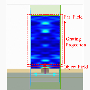
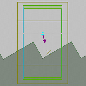
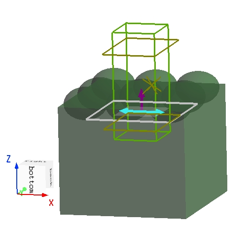
本案例中使用的衍射光栅是在折射率 的基底的上表面上的二维半椭圆球阵列,如下图所示。一个宽带平面波从基底垂直入射到表面光栅,在光栅前后的反射和透射区域形成多个衍射级次。在 方向使用bloch边界条件,只需要一个周期的仿真范围即可模拟无限周期光栅的结果。为了正确进行光栅投影,监视器 方向上的跨度应该超出 FDTD 的仿真范围。
仿真结果
光栅级数的总数
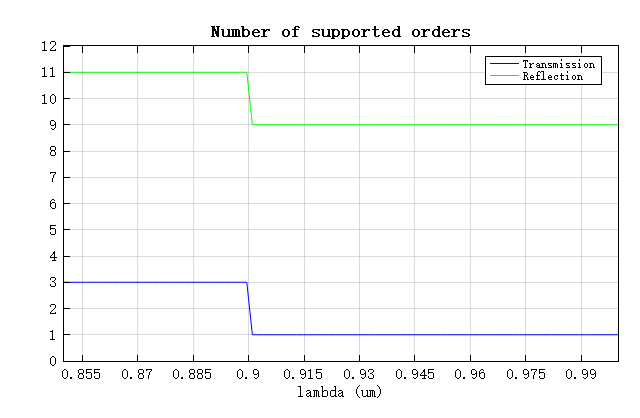
下图展示了光栅的衍射级数的总数随波长的变化情况,可以看到,光栅在较短波长时具有更多的衍射级数,且反射方向的衍射级数数量大于透射方向。这是因为基底的折射率 大于空气的折射率,导致基底中的有效波长更短。
特定衍射级的功率分数
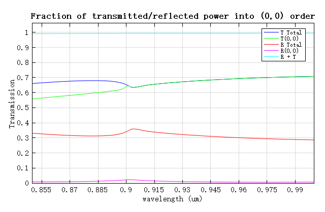
在实际情况中通常需要计算透射或反射功率中有多少被转化到特定的衍射级次中:
透射和反射衍射级中的(0,0)级次的功率分数随波长的变化如下图所示。在透射的(0,0)衍射级中,波长大于 0.9 时透射率 (0,0)与总透射率相同,这是因为此时透射方向仅有一个衍射级,与上图结果一致。而反射的(0,0)级次反射率 (0,0)在整个波长范围内均可忽略不计,意味着大部分的反射功率都被转换到更高的衍射级中。
特定衍射级的衍射角
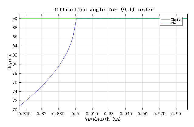
对于周期与入射角固定的光栅结构,除(0,0)衍射级外,其余衍射级的衍射角主要由波长决定。下图显示了透射的(0,1)衍射级次的衍射角随波长的变化趋势。在波长为 0.85 时,该级次以约 70 的角度传播。随着波长的增加, 逐渐增大,表明该级次的传播方向逐渐趋近平行于光栅周期方向。当波长超过 0.9 时, 达到 90 ,该衍射级次转变为非传播模式并消失。
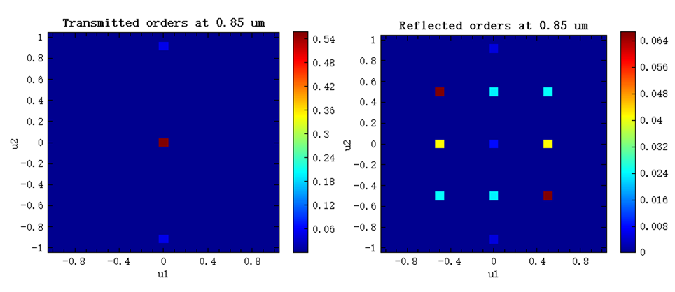
特定波长下的衍射效率
下图显示了在 0.85 处的透射衍射级和反射衍射级的衍射效率分布。结果与上述内容一致。例如,透射和反射分别具有 3 个和 11 个衍射级,且 50%以上的入射光能最终转化到透射的(0,0)衍射阶。