Products
Solvers
Learning Center
Application Gallery
Knowledge Base
Support
License Agreement
Release Notes
Update and New
English
中文
Contact Number
+86-13776637985
Email
info@simworks.net
 Enterprise WeChat
 WeChat Service Account
This section is an introduction to structures.
The software supports the 3D Computer Aided Design (CAD). See CAD.
Users can add and modify structures through script in the software. Please refer to Script.
A simulation should include a structure and a solution algorithm.
Structure is the basic unit of a simulation. The software provides rich structures and structure groups.
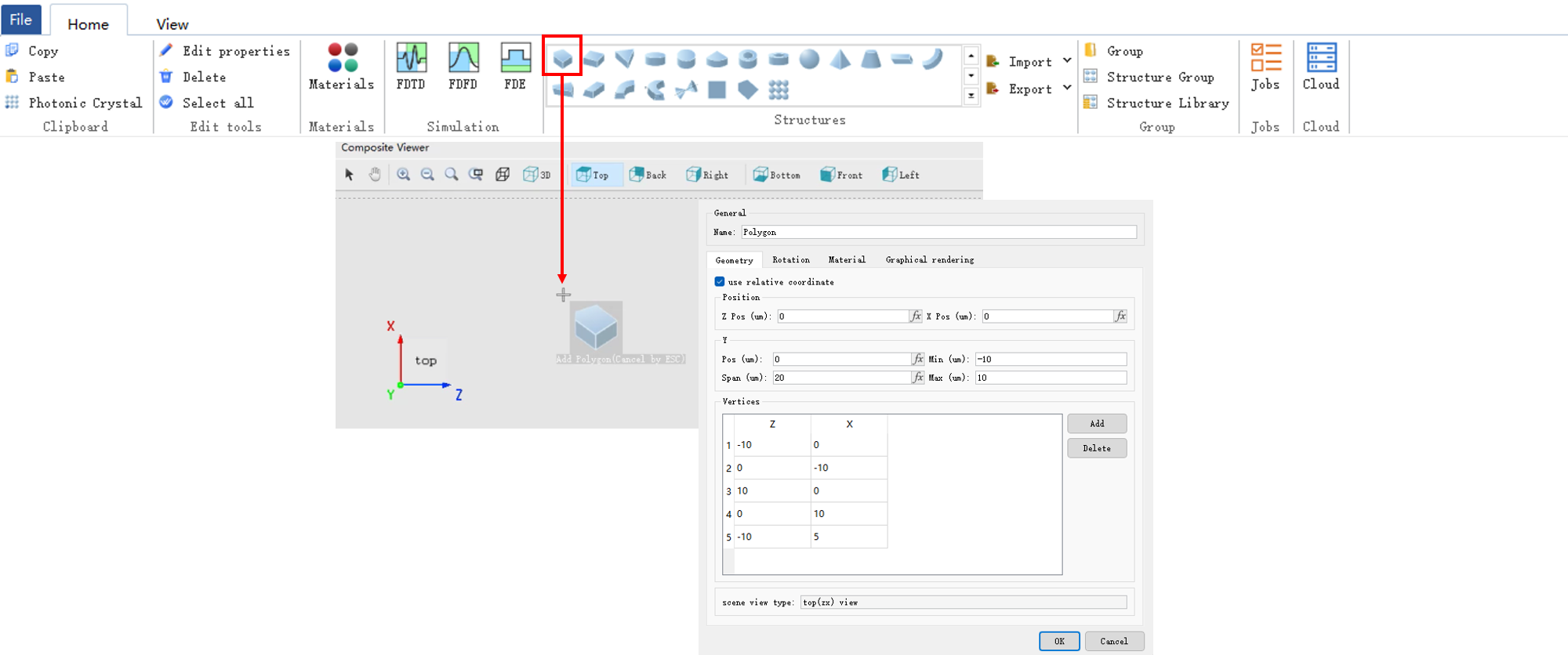
The Geometry tab is used to set the geometry size of the structure.
| Name | Description |
|---|---|
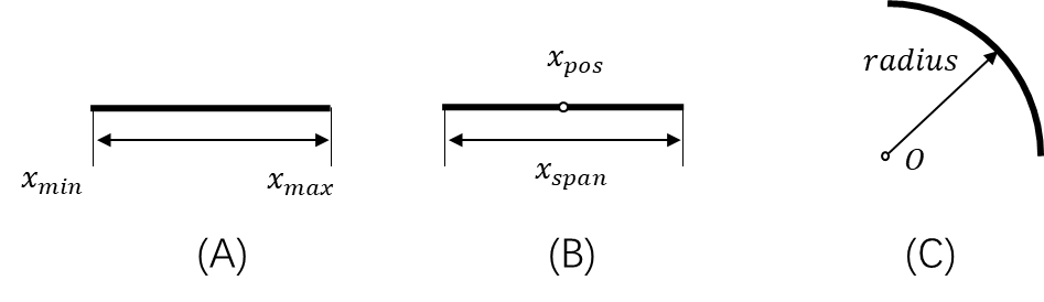
| X/Y/Z pos | Set the structure center. |
| X/Y/Z span | Set the structure scope. |
| Radius X/Y/Z | Set the radius X/Y/Z of the structure. |
| Scene view type | It determines the structure creation direction. |
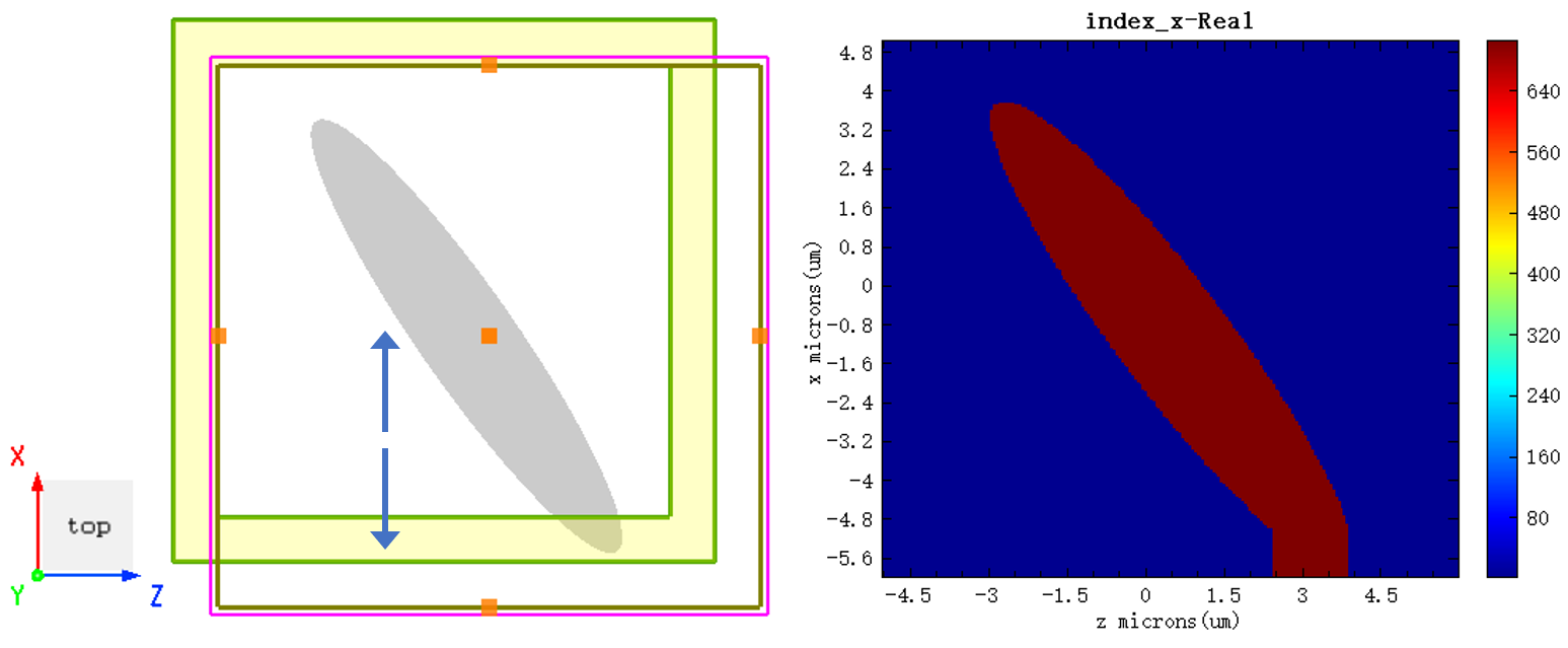
The Rotation tab is used to set the structure rotation.
| Name | Description |
|---|---|
| Rotation axis | Set the rotation axis. The rotation axis is the normal vector of the rotation plane. |
| Rotation | Enter the rotation angle (unit: degree). |
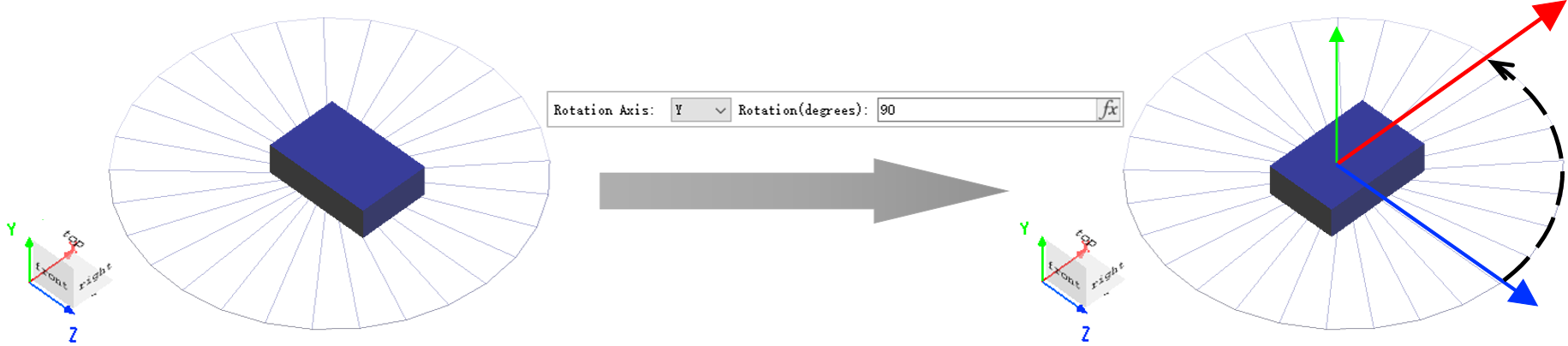
In the world coordinate system of the composite viewer, the forward direction of the coordinate axis is the forward direction of the normal vector of the rotation plane.
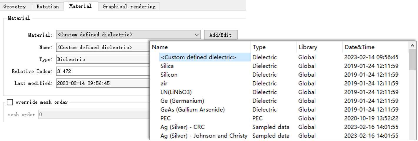
The Material tab is used to set the structure material. The structure without material does not exist (the default material is given at the beginning of the creation of the structure). See Dielectric.
| Name | Description |
|---|---|
| Material | Drop-down menu. Select the structure material. |
| Add/Edit | Add/Edit project materials. |
| Override mesh order | Start mesh level input. |
| Mesh order | Mesh level. Set the order to create mesh. |
The rest items of the default material such as Name, Type, etc. are automatically filled in, which are view-only items.
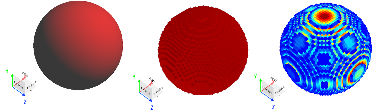
The Graphical rendering tab is used to set the opacity and rendering precision of the structure.
| Name | Description |
|---|---|
| Override default transparency | Select and set the material opacity. |
| Opacity | Set the material opacity: 1: opacity; 0: transparency. |
| Detail points | The rendering accuracy of the structure in the 3D display. The higher the accuracy, the more detailed the rendering effect. |
The following table lists the structure types that are supported by the software:
| Name | Description |
|---|---|
| Polygon class | Polygon, Rectangle, Triangle. |
| Polygon 2D class | Polygon2D, Rectangle2D. |
| Ellipse class | Ellipse, Circle, Sector. |
| Ring class | Circle ring, Ellipse ring. |
| Sphere | Ball. |
| Pyramid class | Pyramid, Cone. |
| Sidewall class | Sidewall linear, Sidewall arc, Sidewall bezier. |
| Waveguide class | Linear waveguide, Arc waveguide, Linear taper. |
| Equation | Use the analytic expressions to build a 2D outline of the structure, and then form a 3D structure through rotation or stretch. |
See Structure groups.
The software provides several methods of checking the created structure. The frequently-used methods are as follows:
When Extend structure through PML is selected on the boundary condition setting interface in the solver and the structure extends beyond the simulation area, the device extends along the axis if using the PML boundary.
The undersurfaces of the structure vary with the selected viewing plane types. In 3D view, select the plane observed through Switch to top (ZX) view as the undersurface of the structure.
In this setting, the component plane can be added in the toolbar of the composite viewer, or through script selection:
(In 3D view, select Switch to top (ZX) view)
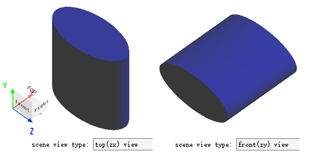
Scene view type is view-only. No modification is allowed. Please use the Rotation tab to change the "Direction" of the built structure.

