Products
Solvers
Learning Center
Application Gallery
Knowledge Base
Support
License Agreement
Release Notes
Update and New
English
中文
Contact Number
+86-13776637985
Email
info@simworks.net
 Enterprise WeChat
 WeChat Service Account
This section describes sources.
After adding a solver, the solver tab will automatically appear, which contains various sources. Users select the desired source and click anywhere in the Composite viewer. Users can modify source settings in pop-up Edit properties interface to complete the addition of source.
Software supports functionality of adding and modifying sources through scripts. See Script.
Software currently supports the following source types:
| Name | Description |
|---|---|
| Dipole source | Used to describe field distribution of an ideal electric/magnetic dipole. For details, see Dipole. |
| Plane source | Used to describe a uniform optical field distribution (with a uniformly distributed complex amplitude field). For details, see Plane. |
| Gaussian source | Used to describe a source with Gaussian incident field distribution. For details, see Gaussian. |
| TFSF source | Total-Field Scattered-Field (TFSF) source is a typical source used to study scattering issues. For details, see TFSF. |
| Mode source | Use an eigenmode solver to solve eigenmodes on incident planes, which are then injected as sources into the simulation region. For details, see Mode. |
| Import source | User-defined source. This option allows users to define sources according to their specific needs. For details, see Import source. |
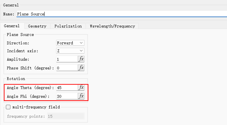
General tab can be used to set amplitude and incident angle of a source.
| Name | Description |
|---|---|
| Amplitude | Source amplitude is set as 1 by default. |
| Phase shift | Used to set phase delay between multiple sources. |
| Angle theta | Polar angle. Angle between direction of source propagation and normal of incident plane. |
| Angle phi | Azimuthal angle. Angle between projection of source in propagation direction onto interface (if light propagates along Z-axis, XY plane represents interface) and positive X-axis. |
You can set incident angle of a source by editing Angle theta and Angle phi in General tab. Angle phi is only valid for 3D simulations.
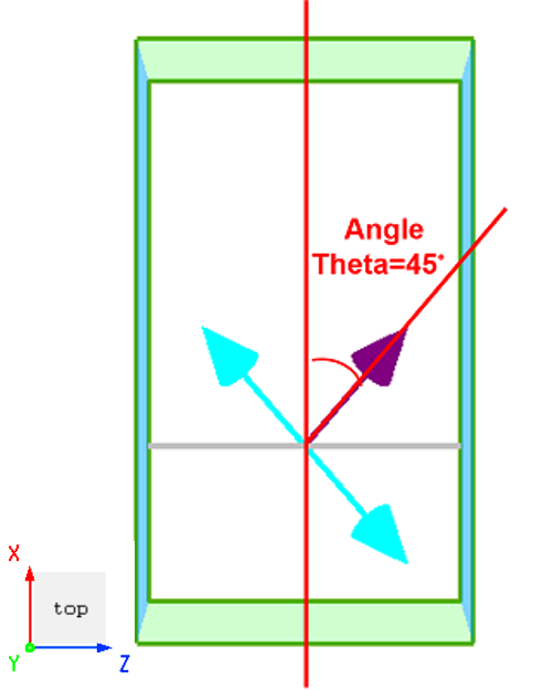
If Angle theta is set to 45 for a plane source with propagation direction in the positive Z-axis direction, ZX plane view is shown in the following figure:
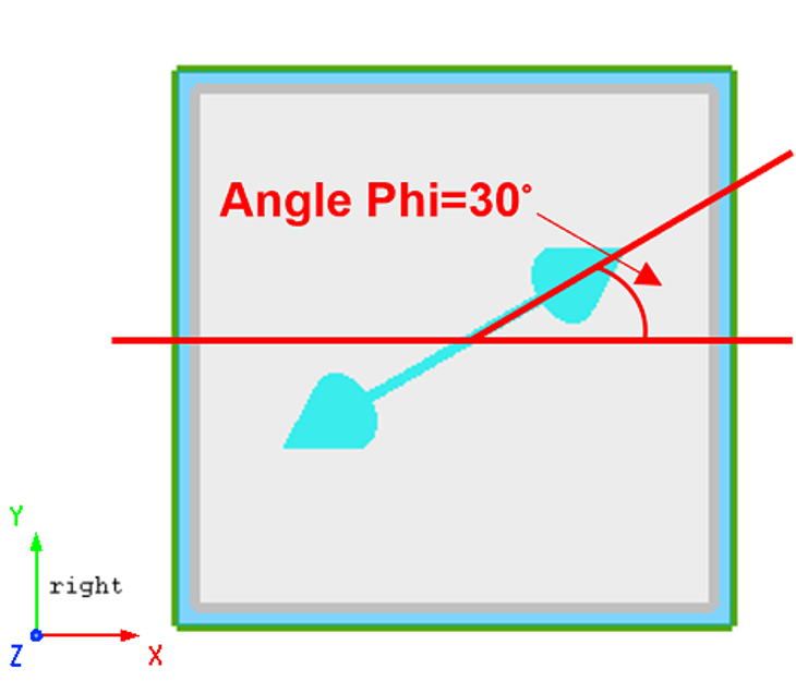
If Angle phi for a plane source is set to 30, YX plane view is shown in the following figure:
Specifically, for a dipole source, Angle theta represents angle between dipole vector and Z-axis, while Angle phi represents angle between the projection of dipole vector and positive X-axis direction.
Geometry tab can be used to set geometric dimensions of a source.
| Name | Description |
|---|---|
| Use relative coordinate | Use relative coordinates. |
| Z/X/Y pos | Center of a source. |
| Z/X/Y span | Range of a source. |
| Cells Z/X/Y | Number of offset units in the Z/X/Y direction. |
Wavelength/Frequency tab can be used to set wavelength/frequency range of a source.
| Name | Description |
|---|---|
| Continuous wave | Continuous wave. |
| Modulated gaussian wave | Modulated Gaussian wave. |
| Select domain | Select Wavelength or Time as the domain of input parameter. |
| Center/Span | Center/Span Used to set center wavelength and wavelength bandwidth. |
| Max/Min | Max/Min Used to set maximum and minimum values for bandwidth. |
| Central frequency | Define central wavelength. |
| Pulse width | Define pulse width which covers the wavelength or frequency range to be simulated. |
| Pulse offset | Defines pulse offset, i.e., time interval between start of the simulation and center of input pulse. Thus, the initial field is close to zero at the start of the simulation. To avoid interruption of the input pulse, the pulse offset should be at least twice the pulse duration to ensure that the frequency distribution is approximately symmetrical near the central frequency of the source. |
| Bandwidth | Define full width at half maximum (FWHM) of source in frequency domain. |
| Pulse type | Two types are available: Standard and Broadband. This is a read-only parameter. |
Software provides wavelength/frequency domain images, which are plotted respectively for:
Time domain signals;
Wavelength domain spectrum;
Frequency domain spectrum.
In Material fitting > Bandwidth range setting tab, wavelength/frequency range of source is displayed by default.
In Monitor > wavelength/frequency tab, the wavelength range of source is displayed after Base on source setting is checked.

