Products
Solvers
Learning Center
Application Gallery
Knowledge Base
Support
License Agreement
Release Notes
Update and New
English
中文
Contact Number
+86-13776637985
Email
info@simworks.net
 Enterprise WeChat
 WeChat Service Account
This section describes the settings for TFSF sources.
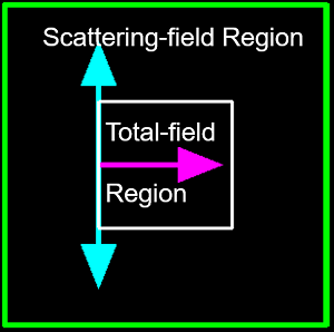
When studying scattering field problems, Total-Field Scattered-Field (TFSF) sources can be employed to directly acquire the scattering fields.
Select the TFSF in the solver tab and create a TFSF source in the Composite viewer, then set further parameters in the Edit properties interface that automatically pops up.
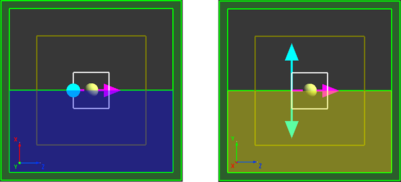
In FDTD, the TFSF source divides the calculation region into two distinct regions:
TFSF sources are often used to study scattering and antenna problems. Typical applications include:
The option of TFSF source is an advanced feature. Users should determine the appropriate source settings according to these instructions to ensure accurate results. Otherwise, incorrect settings may lead to inaccurate results.
The General tab can be used to set the incident axis, amplitude, and other parameters related to a source.
| Name | Description |
|---|---|
| Incident axis | Select the desired incident axis for a TFSF source from the drop-down list. |
| Direction | The propagation direction of a TFSF source, specifically selected as Forward (forward propagation) or Backward (backward propagation). |
For the settings related to the amplitude, phase shift, and rotation of TFSF sources, see the general settings in Source.
The Geometry tab can be used to set the geometric dimensions of a source. See the geometry settings in Source.
The Polarization tab can be used to set the polarization of a source.
| Name | Description |
|---|---|
| Linear polarization(θ) | The polarization angle for linear polarization. |
Wavelength/Frequency tab can be used to set the wavelength/frequency of a source. See wavelength/frequency settings in Source.
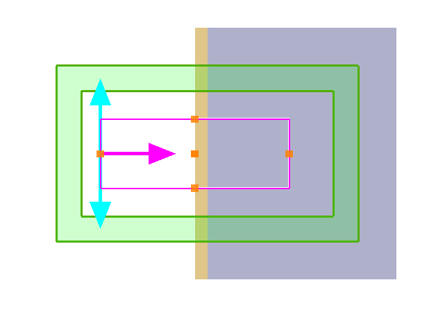
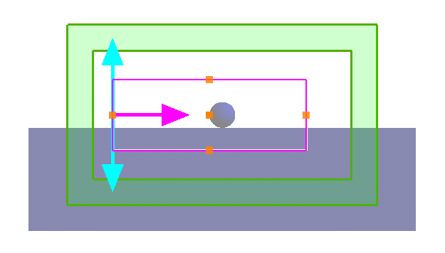
When a TFSF source is added into a project, make sure the following conditions are met:
Valid injection: The wave-vector is perpendicular to the gold and glass layers. Each side of the source undergoes the same refractive index distribution (air-gold-glass) along the propagation direction (from the incident surface to the end surface).
Invalid injection: The incident axis is not perpendicular to the substrate. The upper part of the source is exposed to the air, while the lower part is exposed to the substrate.
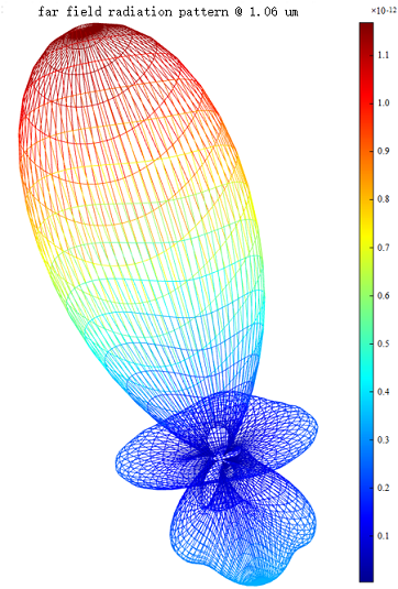
TFSF sources are used to study Mie scattering in this case. For related information, see Mie Scattering. The project is shown as below:
Once the simulation is completed, the scattered field (i.e., the field outside the space surrounded by the TFSF source) is extracted, and the far-field analysis is used to obtain the following polar plot and radiation pattern: