光学材料
光学材料 #
本节是关于光学材料的介绍。
软件中的光学材料,在所有算法(FDTD、FDFD、FDE)中均可以使用。
软件预定义了丰富多样的材料数据和模型,如介电材料、电导材料、模型材料、散点数据的材料、非线性材料、新兴热门材料等,并允许用户添加自定义材料。在光学材料库中,用户可以新增材料,编辑新增材料参数,手动拟合材料模型,检查材料模型拟合效果。
软件支持使用脚本添加和编辑材料,详情请参阅脚本。
光电子学材料 #
定义:复折射率 N #
一般地,引入折射率的虚部κ,使用复折射率N定义材料:
N=n+iκ
其中,n为N的实部,表示通常意义的折射率;κ为N的虚部,表示衰减(κ>0)或增益(κ<0)。
复折射率和复介电常数 #
复介电常数ε=ε1+iε2和复折射率N的关系为:
ε1ε2=n2−κ2=2nκ
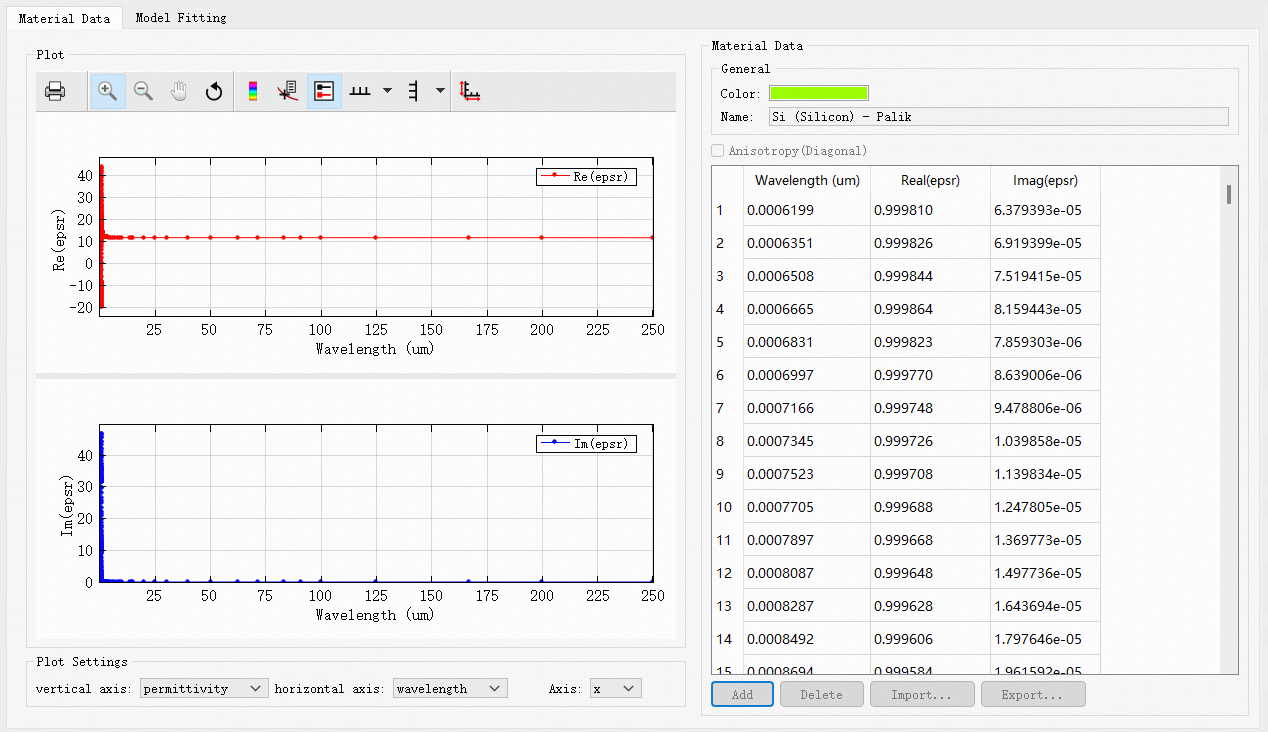
材料的标签 #
材料库中的材料均可以在材料数据页面设置颜色和名称。
| Name | Default | Description |
|---|---|---|
| Color |  |
指定材料的颜色。 |
| Name | Untitled material | 设置材料的名字,为字符串类型。 |
频域特性:色散关系 #
色散关系 #
按照材料折射率是否与频率(或波长)相关,材料可以分为:
- 非色散材料:在一定波段材料折射率为常数;
- 色散材料:材料的折射率是频率(或波长)的函数。添加色散材料时,需明确折射率对应的频率(或波长)范围。
材料拟合 #
通过拟合算法,材料以模型的形式用于工程的仿真。
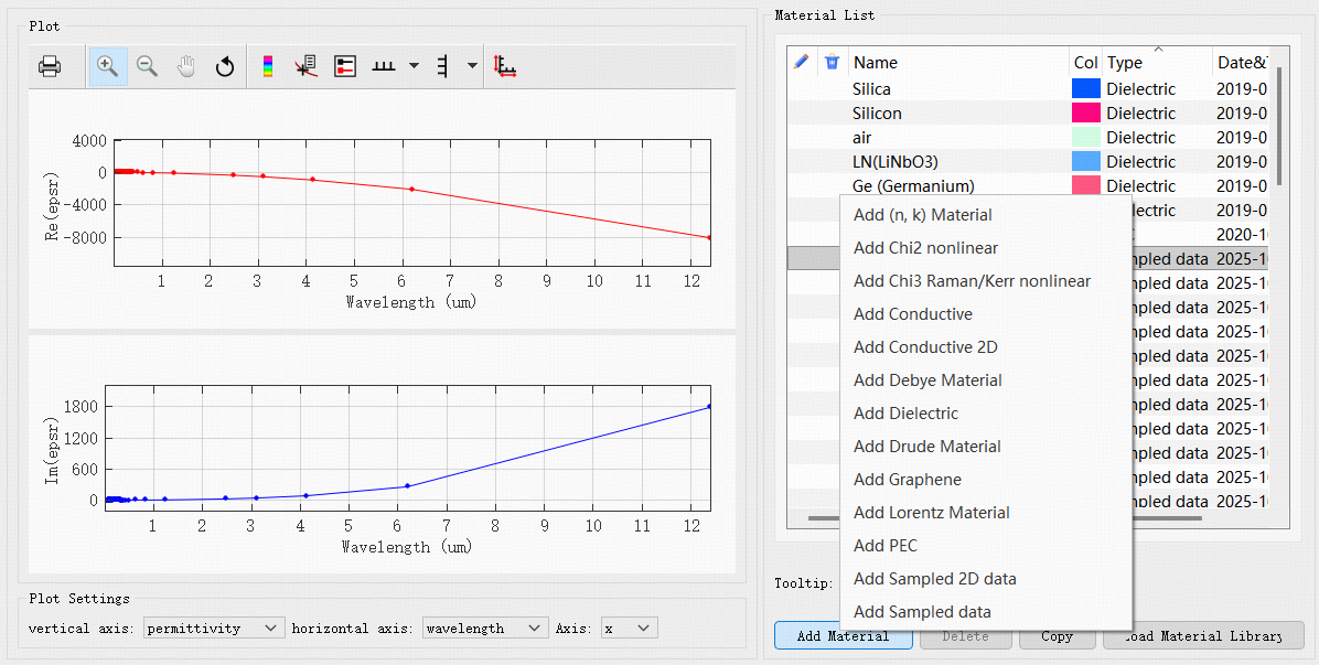
下面为材料拟合窗口:

该窗口展示材料的带宽范围、拟合参数设置、拟合状态等选项卡。其中RMS误差用于评估材料拟合的效果。若需了解更多详细内容,请参阅后文的“材料拟合”部分。
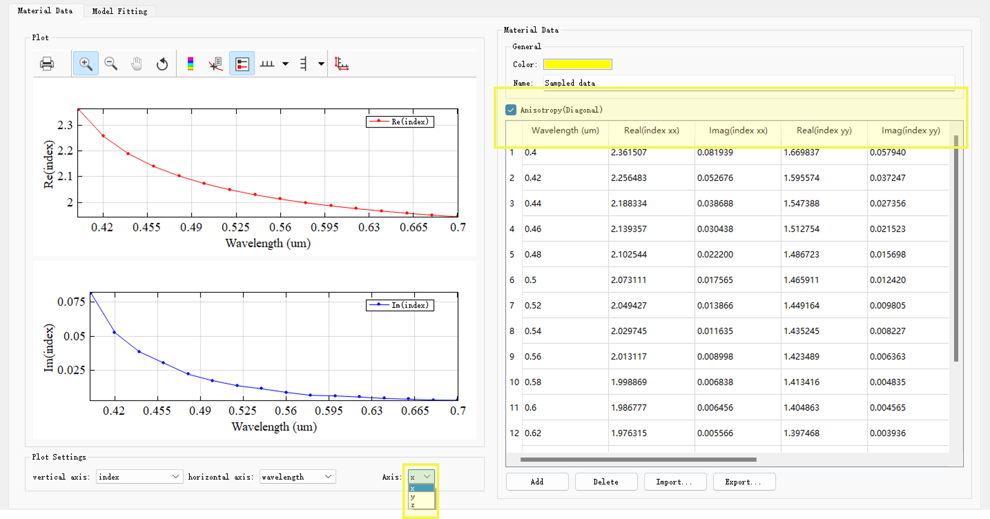
空间特性:各向同性和各向异性 #
软件支持各向同性材料和对角各向异性材料的创建。
其中对角各向异性材料的介电常数的数学表达式为:
ε=⎣⎢⎡εxx000εyy000εzz⎦⎥⎤
在材料数据页面,勾选Anisotropy(Diagonal)即可分别设置εxx,εyy,εzz,该按钮对于所有材料类型均适用(PEC暂不支持);在绘图窗口中,对图像设置中的轴向进行切换,可以查看不同方向的材料数据。
暂不支持一般的各向异性材料,即:
ε=⎣⎢⎡εxxεyxεzxεxyεyyεzyεxzεyzεzz⎦⎥⎤
非线性响应 #
一般而言,任何材料均具有非线性响应特性,因此,非线性响应并不是一种单独的材料类型,为方便描述,本文不区分非线性材料和非线性响应。
在软件中,非线性材料由基础材料和非线性系数构成。
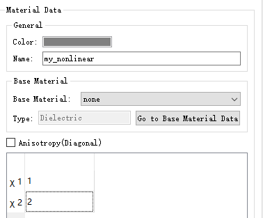
软件支持两种类型的非线性材料:Chi2 nonlinear和Chi3 Raman/Kerr nonlinear。
更多设置细节,请参阅非线性材料
材料和材料库 #
材料类型 #
目前软件支持的材料类型有:
| Name | Description |
|---|---|
| Dielectric | 介电材料,用来描述具有恒定折射率,即折射率与波长无关的材料,详情请参阅介电材料。 |
| (n, k) Material | nk 材料的折射率N=n+iκ,nk 材料用来描述单频点(或中心频点)的材料,详情请参阅(n, k)材料。 |
| Conductive | 电导材料,用来描述电导材料的模型,该材料模型与频率相关,详情请参阅电导材料。 |
| Conductive 2D | 2D电导材料,用来描述2D电导材料的模型,详情请参阅电导材料。 |
| Debye | 德拜材料,用来描述无相互作用的单个粒子(如气体),该材料模型与频率相关,详情请参阅德拜材料。 |
| Lorentz | 洛伦兹材料,用来描述半导体材料模型,该材料模型与频率相关,详情请参阅洛伦兹材料。 |
| Drude | 德鲁德材料,用来描述等离子体/金属材料的模型,该材料模型与频率相关,详情请参阅德鲁德材料。 |
| PEC | PEC即完美导体,用来描述理想导体,详情请参阅PEC。 |
| Sampled data | 使用材料的实验数据,拟合出该材料在指定频段的稳定模型,详情请参阅光学散点材料。 |
| Sampled 2D data | 使用薄膜材料的真实实验数据,拟合出该材料在指定频段的稳定模型,详情请参阅光学散点材料。 |
| Chi2 nonlinear; Chi3 Raman/Kerr nonlinear | 非线性材料,用来描述光学材料的非线性频域响应,详情请参阅非线性材料。 |
| Graphene | 石墨烯材料,是用来描述新兴材料——表面电导石墨烯模型,详情请参阅石墨烯材料。 |
| RLC | RLC材料,用来描述一定电阻(R)、电感(L)和电容(C)的集总元件。 |
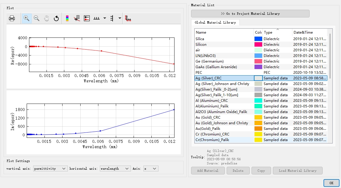
材料库 #
用于存放材料的库即为材料库。
在软件中,我们拥有光学材料库和电学材料库。前者支持在FDTD、FDFD和FDE求解器中使用,后者仅支持在FDCharge求解器中使用。电学材料相比光学材料的属性外,增加了一些电学性质,更多信息请参见有限差分载流子传输(FDCharge)求解器。本节仅介绍光学材料库。
在构建结构时,用户可以在结构的材料选项卡中选取光学材料库中收录的材料。此外,用户还可以根据实际材料特性,在光学材料库选择合适的材料类型添加新的材料。不同的材料类型需要设置不同的材料参数,具体细节请参阅上文材料类型表格。
材料拟合 #
软件通过拟合算法,将材料的实验数据拟合为稳定的材料模型。
材料拟合的参数设置 #
在材料拟合窗口,存在以下设置:
| Name | Default | Description |
|---|---|---|
| Bandwidth Settings | 波长设置范围 | 该页面展示材料的频率/波长范围,默认显示的带宽范围与光源一致。 |
| Tolerance type | RMSE | RMSE(Root mean squared error)和RRSE(Root relative squared error) 是表征拟合误差的最重要参数,定义方式略有不同: RRSE=[i=1∑n(pi−ai)2]/[i=1∑n(aˉ−ai)2] ;RMSE=i=1∑n(pi−ai)2/n。 |
| Tolerance | RMSE:0.1 | 材料拟合允许的最大容差。 |
| Max coefficients | 6 | 材料拟合模型(多项式)允许最高阶数。 |
| Improve FDTD stability | 勾选 | 提高拟合模型的稳定性。 |
| Imaginary weight | 1 | 材料拟合的虚部权重。 |
| Ratio | 20 | 比率,这是PSO的自定义参数之一,默认不需要修改。 |
| Max generations | 240 | 需要运行的最大迭代次数,默认不需要修改。 |
| Generation size | 500 | 每次迭代中的粒子数,默认不需要修改。 |
自动拟合 #
对于材料数据的拟合,软件提供自动拟合材料的方式。
flowchart TD
Choose_SampledMaterial[Choose material] --User define--> MaterialFitting[Material fitting program];

Lambda/Frequency-.Base on source.-> MaterialFitting[Material fitting program];
parameters[RMSE, Max coefficients]-.Default.-> MaterialFitting[Material fitting program];
自动拟合,即:
- 拟合程序所需参数,拟合参数来自默认值,仅需要指定材料即可;
- 在仿真前,自动执行拟合程序。
拟合模型的评估 #
对于拟合结果,软件提供拟合结果的参数和图像,用于对材料拟合模型的评估。
flowchart TD
MaterialFitting[Material fitting program] -->Fitting_status[Fitting status];
MaterialFitting[Material fitting program] -->Figure;

Fitting_status --> parameters2[RMSE/RRSE, Max coefficients];
Fitting_status -->Lambda/Frequency;
Fitting_status -->Others[...];
对拟合模型的评估:
- 结合返回的RMSE/RRSE值和图像,评价拟合模型的拟合效果;
- 若拟合模型不满足仿真需要,则需要修改拟合参数。
自定义拟合 #
软件允许用户修改材料拟合的各个参数,包括高级设置中的参数,来实现对拟合模型的精细调整。但材料拟合功能十分复杂,只建议非常熟悉软件材料拟合设置的高级用户修改,随意调整可能适得其反。
flowchart TD
Choose_SampledMaterial[Choose material] --User define--> MaterialFitting[Material fitting program];

Lambda/Frequency-.Base on source.-> MaterialFitting[Material fitting program];
parameters[RMSE, Max coefficients]-.Default.-> MaterialFitting[Material fitting program];
自定义拟合,即:
- 拟合程序所需参数的定义方式、输入值等,均可以自定义;
- 该过程可能需要多次尝试,直到拟合模型满足仿真需要;
- 自定义拟合界面的波长仅用于模型展示,不会进行 FDTD 计算。
材料和仿真 #
创建材料模型 #
开始仿真前,需确认仿真需要的材料类型,若材料存在于光学材料库中,则可以直接在结构编辑界面添加。
对于其他材料类型,需要用户在光学材料库窗口,点击Add material完成所需模型材料的创建。
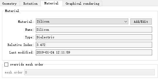
材料赋予结构 #
右键点击结构,进入编辑属性页面,切换到材料页,点击Add/Edit进入工程材料库选择目标材料,完成材料对结构的赋予。
检查材料模型 #
不同的数值求解器对结构的离散化,以及材料数据的赋值,都有各自一套复杂的处理方案。检查材料是仿真检查中的重要一环。
对于建模仿真的不同阶段,软件提供了多种途径,用以材料的检查。
-
光学材料库
在光学材料库中,使用材料拟合选项卡,通过图像或数据来评估材料模型,详情请参阅上文中的材料拟合部分。
-
查看当前网格材料绘制
材料添加进结构后,可以在软件左侧工具栏点击 View the current mesh data ,可以直观地查看材料在三维空间网格上的分布。
-
折射率监视器
通过折射率监视器可准确获取指定空间位置处的材料分布的图像(及数据),方便检查材料创建的正确性。
案例:负折射率材料 #
负折射率材料是一种人造光学结构,折射率在一定频率范围内的是负值,关于负折射率材料的具体细节请参阅负折射率材料。