时域有限差分(FDTD)求解器设置
FDTD设置 #
本节是关于FDTD求解器设置的介绍。
在 Home 选项卡中选择FDTD按钮,在复合视图窗口点击任意位置即可创建FDTD求解器,然后在自动弹出的编辑属性窗口中修改FDTD求解器的设置,即可完成FDTD求解器的添加。
FDTD求解器设置 #
通用设置 #
General标签页用来设置求解器的仿真空间,仿真空间包含仿真维度和几何尺寸。
仿真维度 #
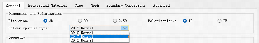
Dimension and polarization选项卡用于设置FDTD求解器的仿真维度。
| Name | Description |
|---|---|
| 2D | 二维仿真模式。TE : TE 偏振,计算Ez、Ex、Hy三个场分量;TM : TM 偏振,计算Ey、Hz、Hx三个分量; Simulation Plane Spatial Type :可选择 Z、X 或 Y 轴作为平面的法线方向。 |
| 3D | 三维全矢量仿真模式,可以计算所有电磁场分量。 |
| 2.5D | 基于二维仿真扩展的准三维仿真方法,通过对三维结构进行合理近似,在保证一定精度的同时提升计算效率。此模式下同样可通过Simulation Plane Spatial Type选项选择仿真平面的空间法向。 |
几何尺寸 #
Geometry选项卡用于设置FDTD求解器的几何尺寸。
| Name | Description |
|---|---|
| Z/X/Y pos | 设置求解器仿真区域的几何中心。 |
| Z/X/Y span | 设置求解器仿真区域在三维坐标方向上的范围。 |
2.5D设置 #
2.5D settings标签页仅当仿真维度为2.5D时启用。
各参数的详细设置,参阅2.5D设置。
背景材料 #
在Background material标签页,提供Background material的下拉菜单,以供用户选择背景材料。
| Name | Description |
|---|---|
| Background material | 背景材料库,包括Global library材料,也可以通过Add/Edit在Project library创建工程材料作为背景材料。 |
选择好背景材料以后,材料的相关信息(Name、Type、Last modified等)会同时被展示出来。
时间 #
Time标签页提供了仿真时间和自动截止的相关设置。
仿真时间 #
Simulation time选项卡提供了仿真时间的设置。
| Name | Description |
|---|---|
| Simulation time | 仿真时间;注意时间单位。 |
| Simulation steps | 仿真步数;整个仿真过程中划分的离散时间步长的数量,只读参数。 |
自动截止 #
Auto shutoff选项卡用于设置仿真自动截止的相关参数。
| Name | Description |
|---|---|
| Early shutoff | 提前截止;勾选激活。 |
| Auto shutoff ratio | 自动截止率;根据当前时刻仿真区域剩余的能量占注入能量的比率来判断是否提前结束仿真。 |
| Numerical divergence | 数值发散的判定;勾选激活。 |
| Auto shutoff maximum threshold | 仿真发散判定截止的最大阈值;判定仿真中剩余的能量和注入能量之比,一旦超过该阈值,仿真被认定为发散,自动结束。 |
| Per time steps(sampled time) | 检查自动截止率的采样时间;即仿真过程中在多少个时间步长之后进行一次采样,软件会在采样时间步上检查仿真中剩余的能量是否满足提前结束仿真的条件。 |
网格 #
Mesh标签页提供了求解器的网格设置。
各参数的详细设置,参阅网格。
边界条件 #
Boundary conditions标签页提供了求解器的边界条件设置。
各参数的详细设置,参阅边界条件。
高级设置 #
Advanced标签页提供了求解器的高级设置。
设置仿真带宽 #
默认情况下,材料拟合基于光源的波长范围进行。如果用户需要拟合超出光源范围的材料模型,则需要设置仿真带宽( set simulation bandwidth )来实现。设置仿真带宽后,软件将在指定的带宽范围内自动进行材料拟合,而不局限于光源的波长范围。这对于会激发光源波长范围之外光的非线性效应尤为重要。此外,重新设置仿真带宽后,该选项也将影响非均匀网格的生成,以及监视器的带宽设置等。
生成网格 #
Mesh generate的设置包括:
| Name | Description |
|---|---|
| Force symmetric x/y/z mesh | 强制x/y/z方向的网格对称;网格划分只考虑仿真区域的正半轴部分,负半轴部分的网格是正半轴部分网格的复制。该选项对结构对称的仿真有意义。 |
| Override bandwidth for mesh generation | 用于自定义生成网格的带宽;该选项允许按照用户自定义的波长范围生成仿真网格。 |
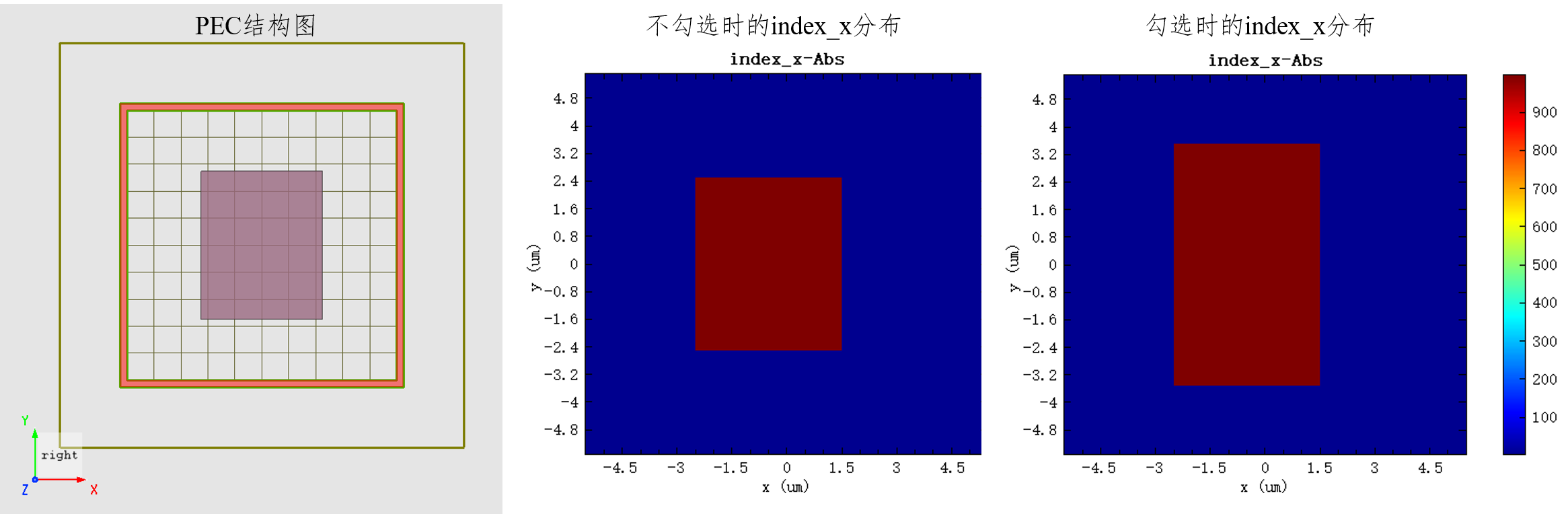
| Snap pec to yee cell boundary | 该功能强制要求所有PEC结构必须与Yee网格单元边界对齐,确保PEC结构界面处的电场分量均保持切向分布。此选项默认勾选,建议在天线工程中始终勾选此选项,以提高辐射效率的计算。 |
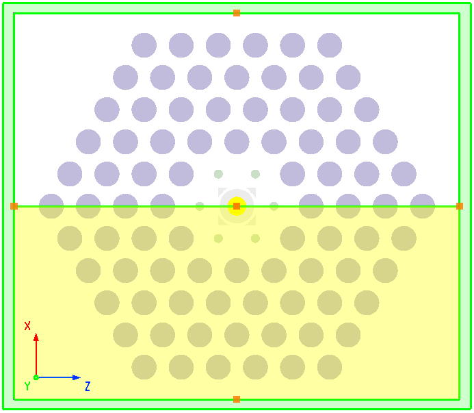
对于一些结构对称的仿真,使用Force symmetric x/y/z mesh就显得尤为关键,比如在缺陷光子晶体共振腔中,需要保持网格对称,尽可能避免因网格不对称引入数值误差,从而保障仿真结果的准确性和可信度。
默认情况下,非均匀网格根据光源的波长范围生成仿真网格,但是对于仿真非线性效应的工程,这种默认设置可能忽略了非线性产生的高频分量,从而在仿真中引入系统误差。为避免此问题,用户可以勾选 Override bandwidth for mesh generation 选项,强制使用合适的波长范围来生成非均匀网格。该选项仅影响非均匀网格的生成,并具有最高的优先级,即生成非均匀网格所依据的波长范围优先级为:Override bandwidth for mesh generation > set simulation bandwidth > source wavelength。
勾选 Snap pec to yee cell boundary 选项可消除PEC界面法向电场分量归零处理引起的数值复杂性。该功能多用于天线辐射类工程应用,对PEC边界的模式求解同样不可或缺。在实际仿真中,为实现精确对齐,软件在生成仿真网格时会对指定的PEC边界进行自动校准,允许最大偏移量为Yee单元格尺寸dx的1/2。
如下图中所示,PEC结构在横向上超出网格线不足dx/2时,软件维持原始网格生成(PEC边界贴合内部网格线);而当纵向上超出网格线dx/2时,会自动向外拓展,使得PEC边界贴合外部网格线。
保存瞬态场 #
当勾选Real-time display of slice fields以后,需要设置的参数有:
| Name | Description |
|---|---|
| Save time point | All sampling time steps:全部的采样时间步长,根据用户设置的采样时间步长,仿真过程中在特定时间点进行数据采样或记录仿真结果。 |
| Sample type | 选择瞬态场的采样方式。Step:瞬态场按时间步长进行采样;Time:瞬态场按物理场实际时间进行采样(单位为ps)。 |
| Sample time steps/sample time(ps) | 根据选择的sample type类型不同设置不同。Sample time steps:在仿真过程中进行采样的时间步长间隔,即在多少个时间步长之后对场进行一次采样或记录结果;Sample time(ps):在仿真过程中进行采样的实际物理场的时间间隔,即在物理场在过去多少时间(单位为ps)后对场进行一次采样或记录结果 |
| Total sample time steps | 按照两种时间采样方式计算在运行完仿真总时间所需要的采样次数 |
| Sample time steps match auto shutoff | 采样时间步长与自动截止相匹配;当该选项卡激活后Sample time steps 选项卡处于只读状态。 |
当设置完成这些选项后,在FDTD仿真控制面板Simulation control panel中还可以进一步设置,详见FDTD仿真控制面板设置。
时域场属性 #
时域场传输中,Use complex field FDTD将计算复数形式的时域场。