创建结构
创建结构 #
本节是关于软件中一些复杂结构创建的介绍。
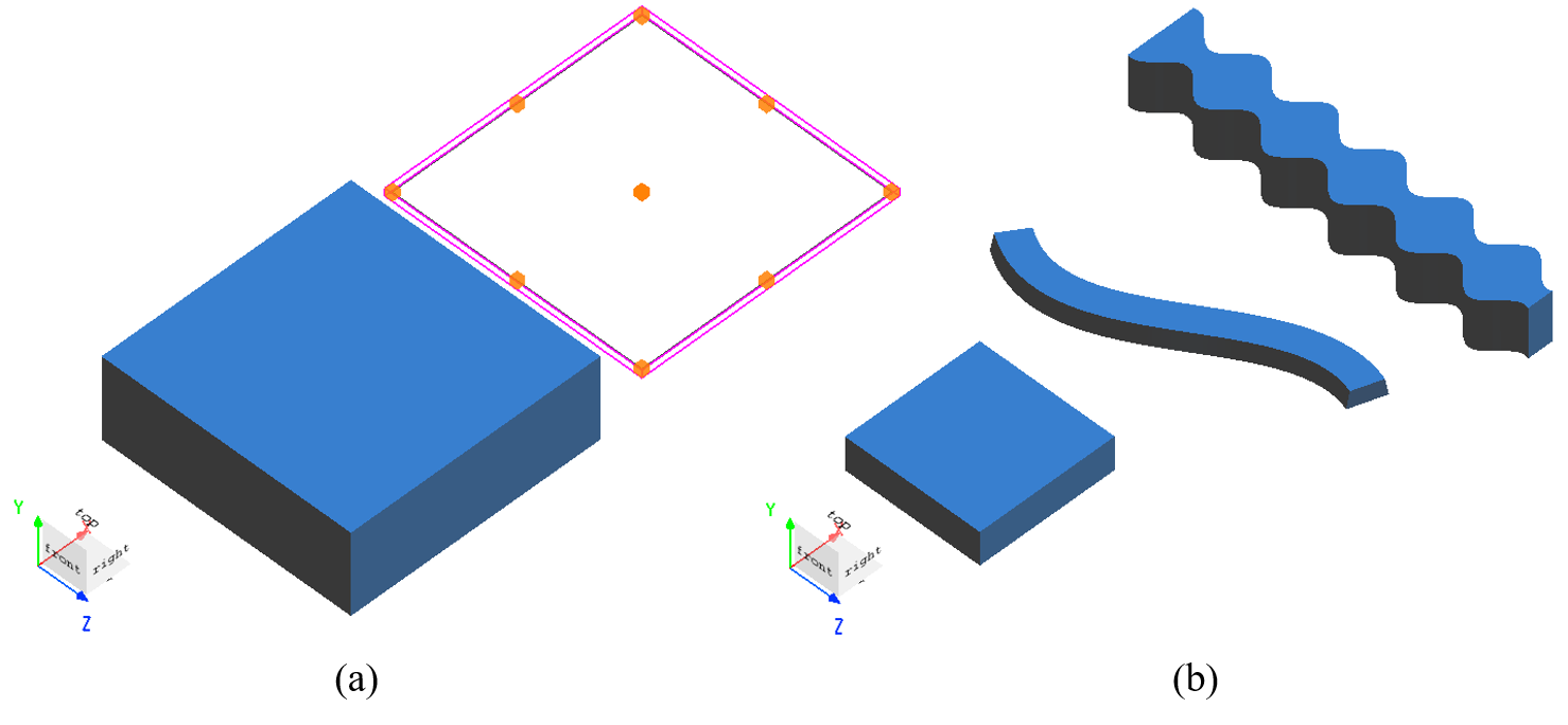
软件提供丰富的结构类型,满足用户对于复杂结构的建模需求。按照维度可以将结构分为二维结构和三维结构,如图(a);按照结构外形,分为简单几何体结构、曲线(贝塞尔曲线)结构、函数构建的拉伸(或旋转)结构等,如图(b)。此外,软件还支持通过导入曲面数据文件来创建自由曲面结构。
创建 2D 结构 #
2D 结构是一类特殊的结构,该结构在法向量方向没有厚度。该结构是软件对超薄材料的理想化近似,可应用于不同的仿真场景。
软件支持通过脚本添加 2D 多边形结构,用户可以根据实际需求通过脚本创建复杂的结构。下面通过两个案例展示 2D 复杂结构的创建。
案例:2D 圆环 #
下面的代码为用脚本添加 2D 圆环结构:
Rin = 0.5e-6;
Rout = 1e-6;
res = 100;
xin = Rin.*cos(linspace(0,2*pi,res));
yin = Rin.*sin(linspace(0,2*pi,res));
xout = Rout.*cos(linspace(0,2*pi,res));
yout = Rout.*sin(linspace(2*pi,0,res));
V = [xin,xout;
     yin,yout];
add2dpolygon;
set("name","2d ring");
set("vertices",V);
运行脚本后,创建的结构如下图所示(图片已做适当处理):

案例:十字孔 #
下面的代码为用脚本添加 2D 十字孔结构:
x_span = 2e-6;
y_span = 2e-6;
W = 1e-6;
L = 0.4e-6;

x = [W/2;L/2;L/2;-L/2;-L/2;-W/2;-W/2;-L/2;-L/2;L/2;L/2;W/2];
y = [L/2;L/2;W/2;W/2;L/2;L/2;-L/2;-L/2;-W/2;-W/2;-L/2;-L/2];

V = [x,y;
     W/2,0;
     x_span/2,0;
     x_span/2,-y_span/2;
    -x_span/2,-y_span/2;
    -x_span/2, y_span/2;
     x_span/2, y_span/2;
     x_span/2,0;
     W/2,0];
add2dpolygon;
set("name","2d cross hole");
set("vertices",V);
运行脚本后,创建的结构如下图所示(图片已做适当处理):

弯曲结构 #
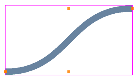
案例:S 弯曲波导 #
编辑结构 #
创建完侧壁贝塞尔结构后,如需编辑结构参数,可在对象树中右键点击该结构或在复合视图中双击该结构,即可打开编辑窗口。
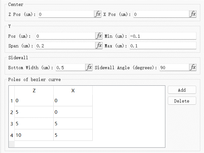
侧壁贝塞尔结构的参数编辑窗口,Sidewall选项卡的功能如下表:
| Name | Description |
|---|---|
| Bottom width | 结构底部的宽度。 |
| Sidewall angle(degrees) | 结构侧壁倾斜角度。 |
Poles of bezier curve选项卡是用来设置侧壁贝塞尔结构的极点。
更多几何选项卡的设置请参阅结构的设置。本案例中参数的设置如下图所示:
结构检查 #
创建完成后的S弯曲波导结构如下图所示:
公式控制的结构 #
编辑结构 #
创建完Equation结构后,对该结构的几何尺寸进行设置,请参阅结构的设置。
结构设置 #
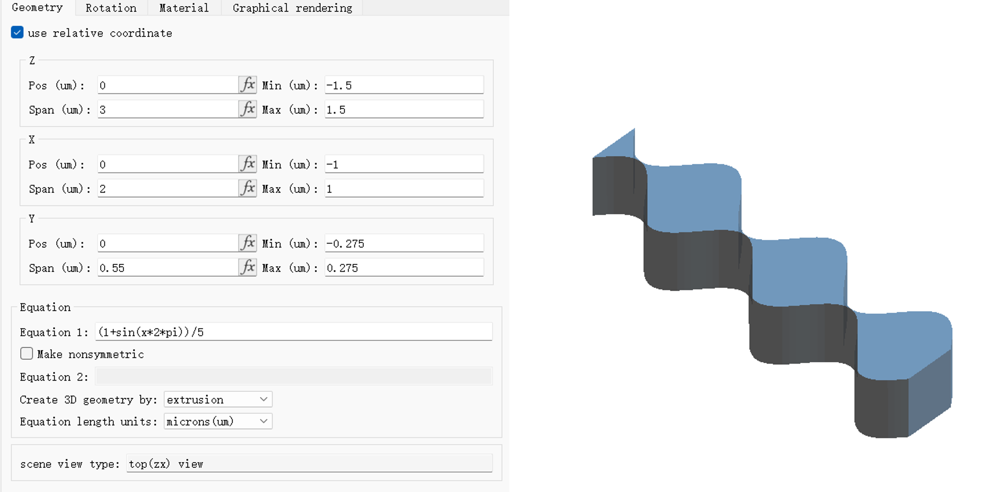
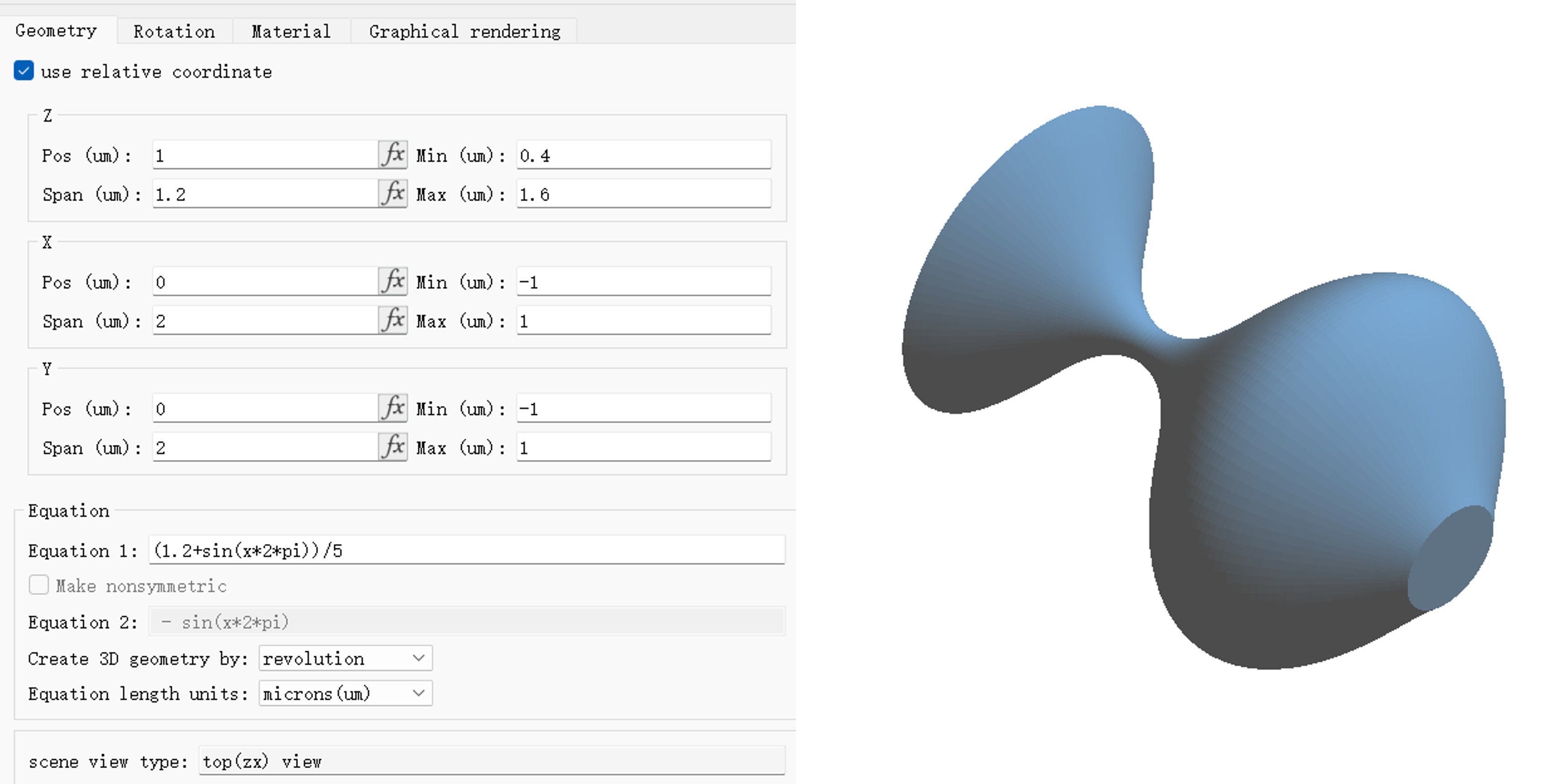
Geometry标签页Equation选项卡用来设置构建结构的方程
| Name | Description |
|---|---|
| Equation 1 | 定义上方区域的方程。 |
| Make nonsymmetric | 仅在通过创建拉伸结构时启用。 |
| Equation 2 | 定义下方区域的方程,当Make nonsymmetric处于勾选状态时启用该项。 |
| Create 3D geometry by | 选择旋转或拉伸。 |
| Equation length units | 方程中使用的单位。 |
案例:创建拉伸结构 #
添加Equation结构后,结构的几何设置和方程设置如下图所示,参数设置完成后,在复合视图中查看结构视图。
案例:创建旋转结构 #
添加Equation结构后,结构的几何设置和方程设置如下图所示,参数设置完成后,在复合视图中查看结构视图。
导入曲面结构 #
本软件支持通过 .txt 文件导入表面高度矩阵数据生成自由曲面结构。这一功能适用于建模复杂的非规则表面,如原子力显微镜测得的数据。
文件格式 #
文件格式如下表所示,文件中可以使用空格、逗号或制表符作为分隔符,各列不必对齐。表格中的 Z(x,y) 为表面的高度信息,m, n 分别代表 x, y 轴的数据范围。
| 描述 | 文件格式 |
|---|---|
| 文件中包含x和y数据 |  |
| 文件中不包含x和y数据 |  |
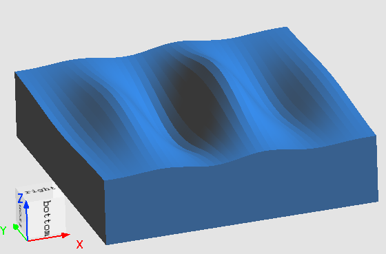
案例:导入自由曲面结构 #
按照文件格式要求准备好.TXT文件:
nx = 50;
ny = 40;
x = linspace(-6,6,nx);
y = linspace(-5,5,ny);
[X,Y] = ndgrid(x,y);
Z = exp(-(X.^2+Y.^2)/4.^2) .* sin(pi*Y/2);
filename = "usr_surface.txt";

# write the data to file
writem(filename, Z);
fclose(filename);
点击Home选项卡中的Import,并选择Surface选项打开表面数据导入窗口。
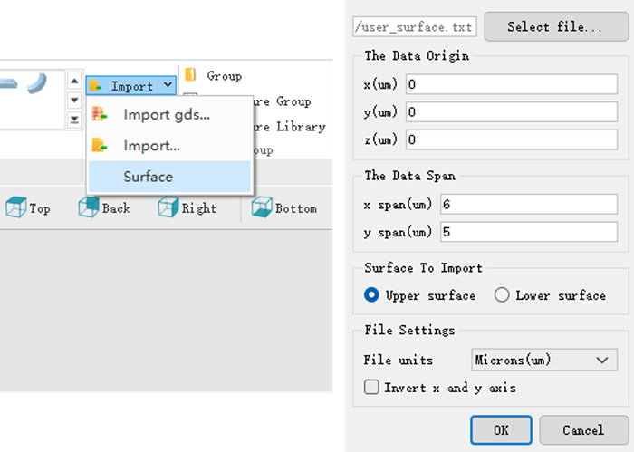
- Select file: 选择要导入的数据文件。
- The Data Origin:设置要导入的表面数据在全局坐标中的原点位置。
- The Data Span:定义导入的表面区域的大小。如果文件中包含了 x 和 y 数据,则此选项不可调节。
- Upper surface:曲面从结构顶部开始生长。数据中 Z(x,y)>0 表示结构向外延伸,Z(x,y)<0 表示结构向内挖空。
- Lower surface:曲面从结构底部开始生长。数据中Z(x,y)>0 表示结构向内挖空,Z(x,y)<0 表示向外延伸。
- File units:选择文件中数据的单位。
- Invert x and y axis:选中复选框表示将 x 和 y 轴互换。