English
中文
Contact Number
Email
 Enterprise WeChat
 WeChat Service Account
This section describes the CAD interface and related operations.
Computer Aided Design (CAD) is one of the important features provided in this software.
The Composite Viewer is used as the main window to perform CAD tasks. In addition, the Objects Tree clearly shows the hierarchical relationships between objects.
The interfaces related to modeling are shown in the figure below:
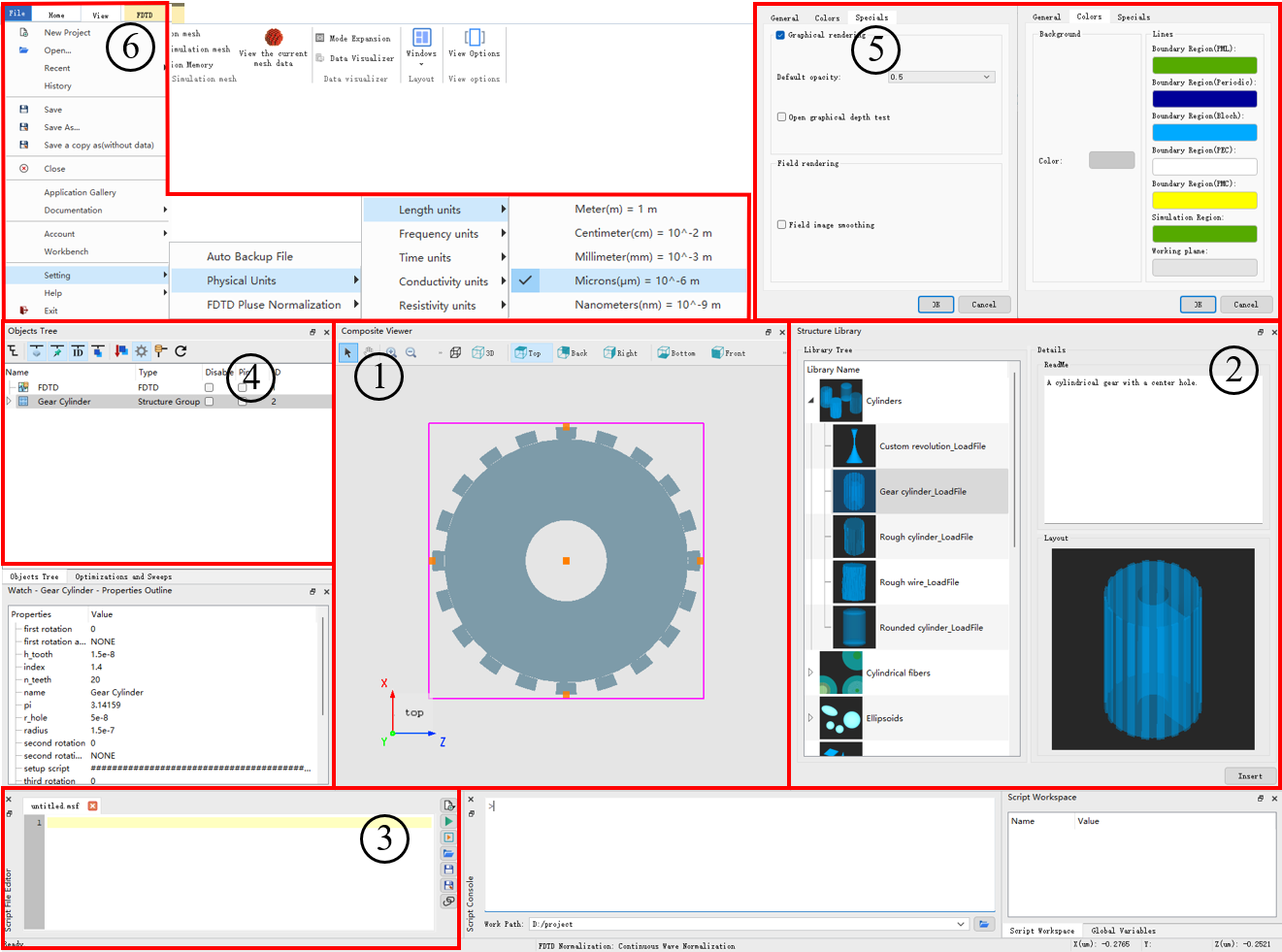
The marked items in the above figure are explained as follows:
| Number | Name | Description |
|---|---|---|
| 1 | Composite viewer | This is the Comprehensive viewer, which includes the structural view, toolbar, and coordinate system icons. |
| 2 | Add structures | This is the Structure library, which allows you to add structures or structure groups. See Structure and Structure Group for details. |
| 3 | Script file editor | This is the Script editor, which allows you to edit script programs. See Script for details. |
| 4 | Objects tree | This is the Objects tree, which contains a tree structure composed of structures, solvers, sources, monitors, etc. See Objects Tree for details. |
| 5 | View | This is the View interface, which enables view settings (color, depth test, etc.). |
| 6 | Setting | This is the Setting interface, which can be used to define the unit, pulse normalization, and other parameters. |
For the structure of an object, you are allowed to perform the following basic operations:
For example, in the Composite Viewer window, you can perform different operations to manipulate and adjust a structure, such as panning, zooming, and view conversion. These operations can be achieved by clicking buttons on the toolbar, as well as using mouse shortcuts and touchpad shortcuts.

| Translate | Rotate | Scale | Select | |
|---|---|---|---|---|
| mouse | drag  |
drag  |
 |
|
| touchpad | shift+  |
alt+  or or option+ |
 or or |
 or or  |
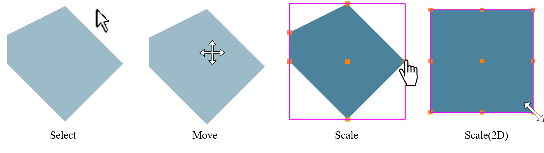
Regardless of the method of operation, please note the change of the actual mouse icon displayed as shown below. For more precise operations, you can modify it on the geometric and spatial parameters page.
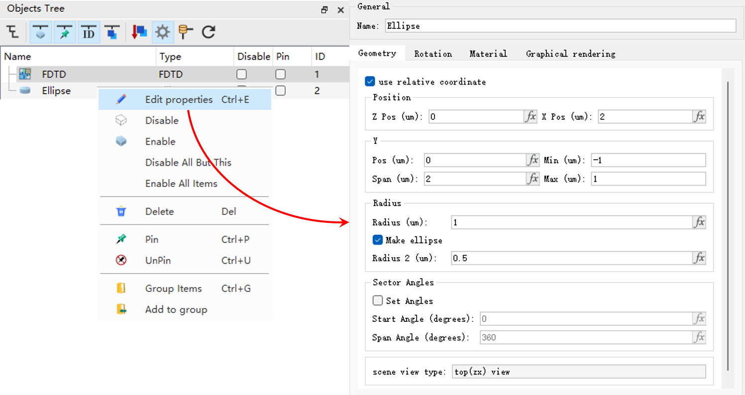
Right-click the desired structure in the Objects Tree. Then you can edit the geometric parameters associated with the selected structure.
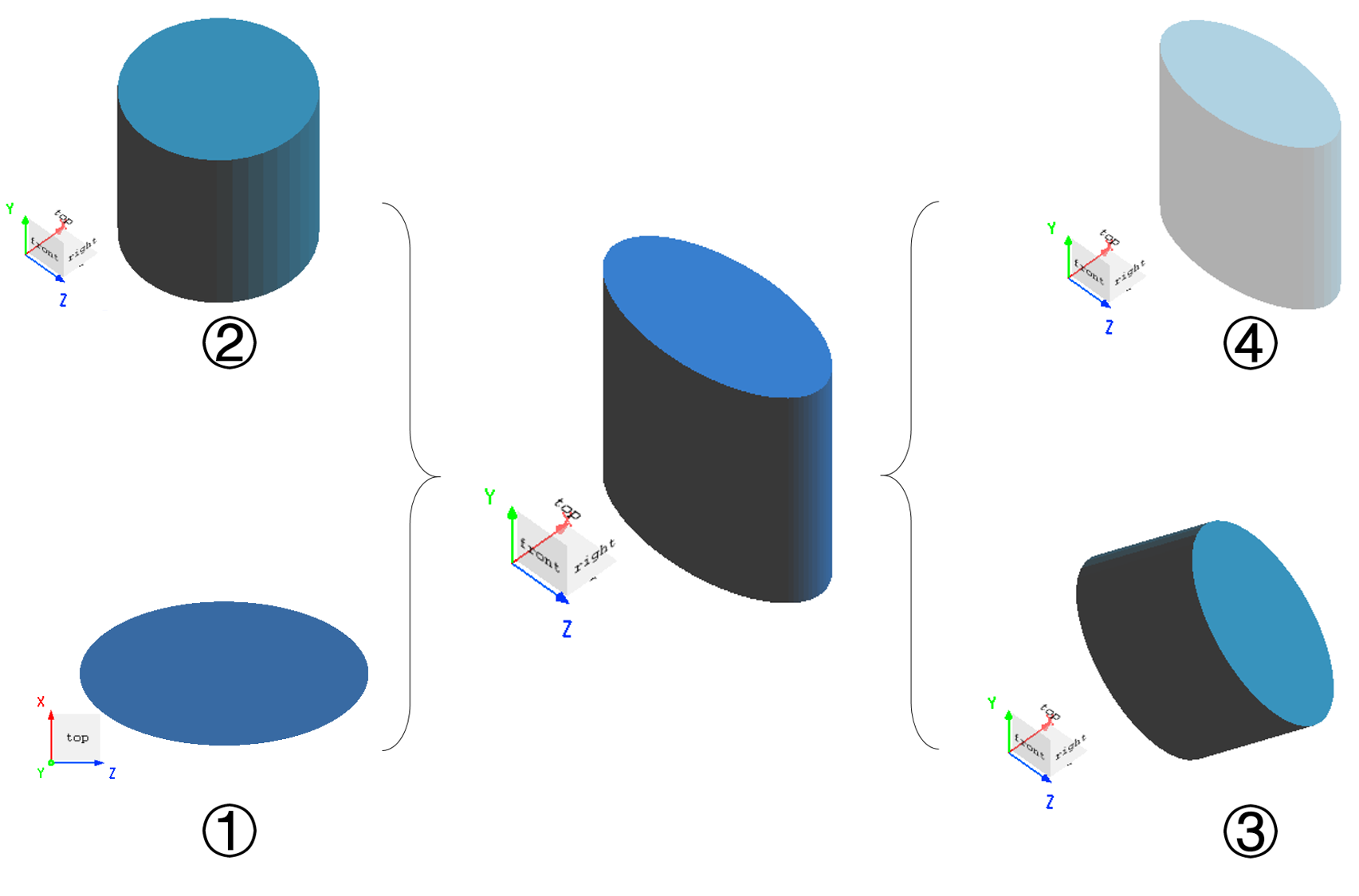
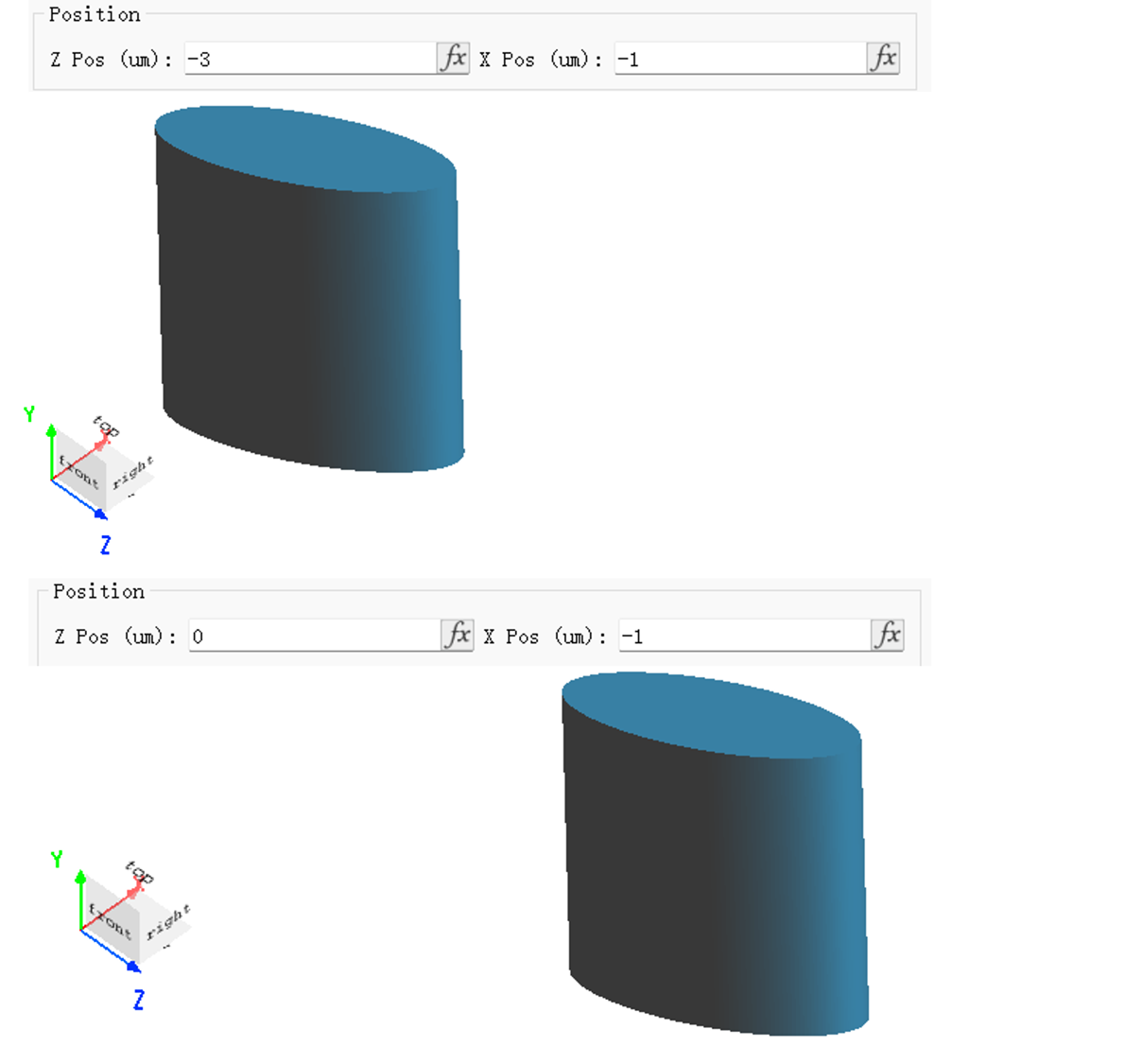
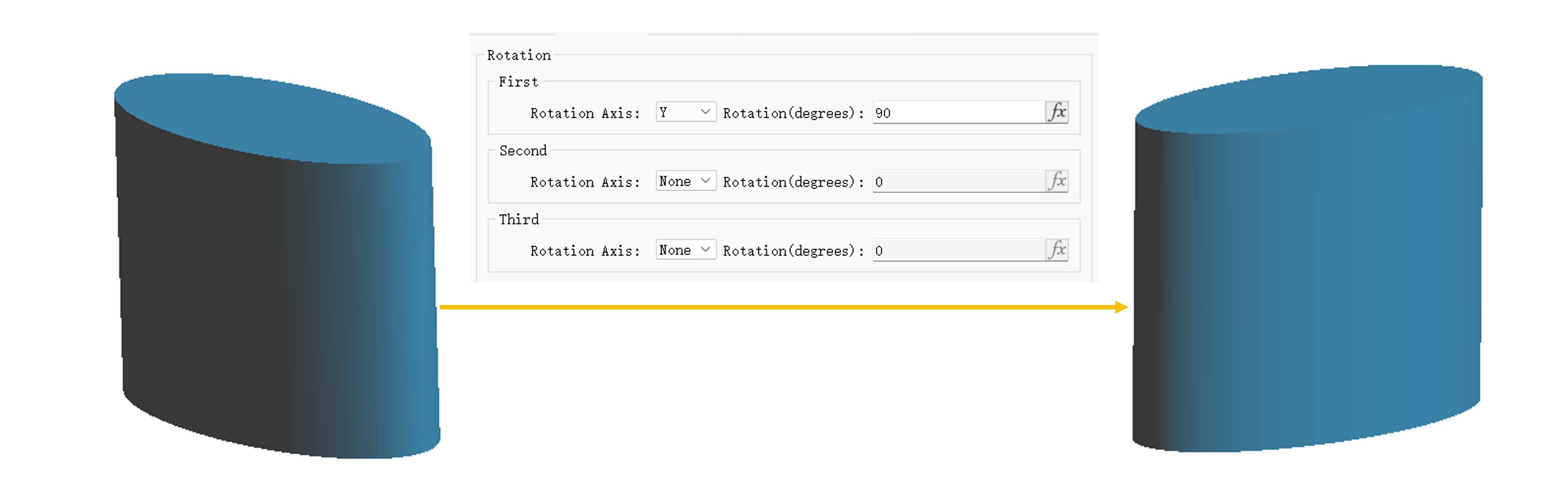
Spatial operations on structures mainly include:
The visual effects of CAD models are displayed in the Composite Viewer Window. You can change the visual effects through the following operations:
| Name | Description |
|---|---|
| Orthographic projection | / |
| Color | Color setting, which allows you to specify the background color, boundary region color, etc. |
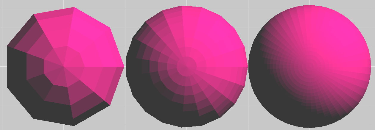
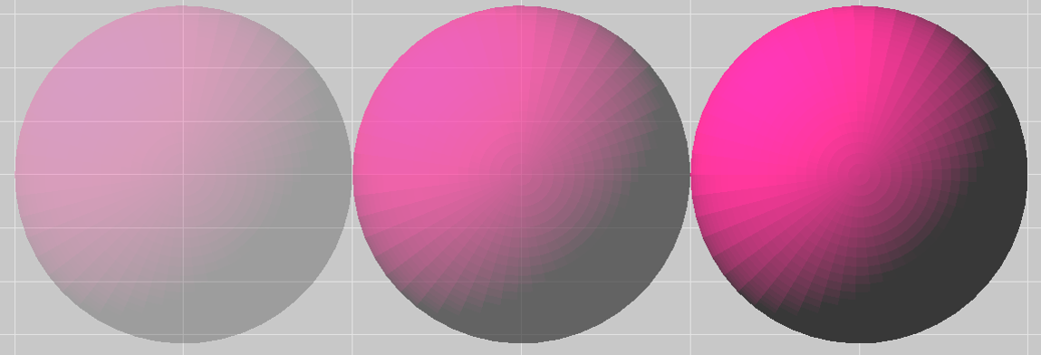
| Graphical rendering | This option is preselected by default. |
| Default opacity | The default value is 0.4. |
| Open graphical depth test | Enabling the depth test functionality. |
| Field image smoothing | / |