Y 型分束器
前言
Y 分束器是集成光子器件中一种非常重要的单元器件,它有非常广泛的应用,如波导干涉仪、调制器、光开光、光分束器等。以 Y 分束器为基本单元所构成的光功率分束器是集成光子系统中不可替代的器件,它可将光功率按预定的比例分配给两个或两个以上的输出设备。从结构上划分,Y 分束器可以分为对称型和非对称型,本案例中使用 FDTD 仿真一个对称型 Y 分束器的插入损耗、传输功率以及 S 参数。
仿真设置
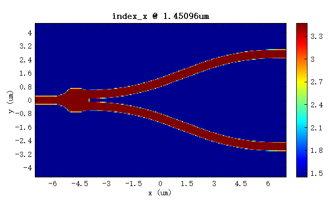
由于 Y 分束器放置在玻璃中,两者相互重叠,FDTD 求解器中使用Mesh Order来确定仿真时重叠部分使用的材料,数值越大优先级越高。因此,本案例中,Y 分束器材料 Si 的Mesh Order被设置为 1, 的Mesh Order被设置为 0。本案例中的 Y 分束器上下对称,使用force symmetric y mesh功能可以保证器件上下两部分的网格分布一致。查看任意波长下器件的index分布,即可验证网格分布是否符合仿真需求。下图为该 Y 分束器在波长为 处的 index_x 分布图,可以看出在仿真中构建的 index 分布也是上下对称的,符合仿真需求。
仿真结果
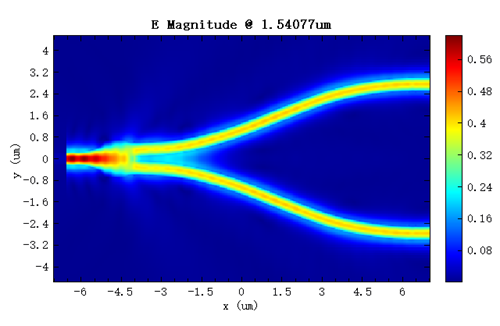
当光从左侧端口输入时,由于该器件上下对称,分支区域的两个端口中光强应该相等,下图为Frequency-Domain Field and Power(FDFP)监视器中得到的光从左侧端口输入时器件中的稳态场分布图以及端口 2 和端口 3 的透过率 T。如下右图中所示,两个输出端口的透过率几乎相等(相差在 7.4E-08 以内)。

参数分析
S 参数是复振幅反射和传输系数,用于描述器件不同端口之间的输入/输出关系。附件工程中包含一个已经设置好的 S 参数矩阵扫描任务,其中添加了三个端口的两个模式,总共需要进行 6 次模拟。运行扫描后可以通过脚本绘制出在 TE1 和 TM0 模式下,从端口 1 到端口 2 和端口 3 的归一化传输功率(S 参数绝对值的平方)和插入损耗,如下图:
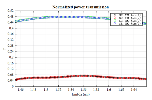
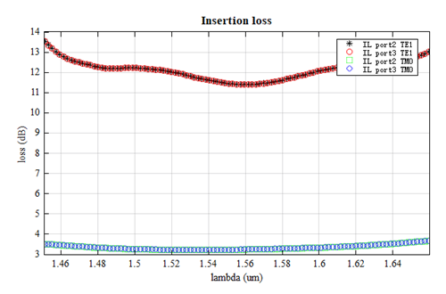
如上第一张图中所示,S21 的透过率与 S31 对应模式的透过率相等,所以案例中 Y 分束器的分光比约为 50-50;第二张图中可以看到在工作带宽内两个端口 TM0 模的插入损耗都小于 4dB,TE1 模的插入损耗在 11-14dB 之间,所以本案例中 Y 分束器对于基模(TM0)的插入损耗很小。