线栅偏振器
前言
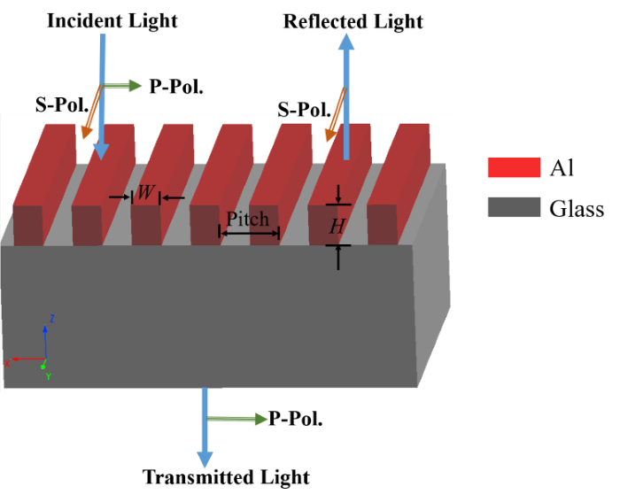
线栅偏振器(Wire Grid Polarizer,WGP),是一类由亚波长周期的金属(如金、银、铝等)光栅组成的偏振器。WGP 因其结构紧凑、光亮度高、偏振消光比(Polatization Extinction Ratio,PER)高、视场宽、易集成化等优点,在光开关、光学显示和成像系统等领域具有广阔的应用前景。本案例复现 Ahn 等人[1]的工作,其结构示意图如下所示,通过控制光栅间距、占空比和铝光栅的高度,可以调整 PER 和传输等光学特性。本案例将研究线栅偏振器在可见光波段下对不同偏振光的传输特性。
仿真设置
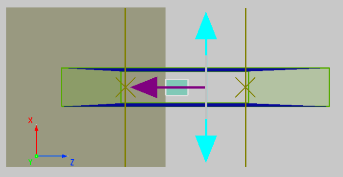
本案例采用 2D FDTD 仿真,由于线栅偏振器是周期性的,在仿真当中构建一个单元结构,使用周期性边界条件Periodic,可以节省计算时间。WGP 由线宽 (光栅单元间距 )、厚度 的铝制均匀线栅组成,衬底材料为玻璃。其结构如下图所示。对光栅区域,使用 的自定义网格,提高仿真结果的精度。
- 光栅
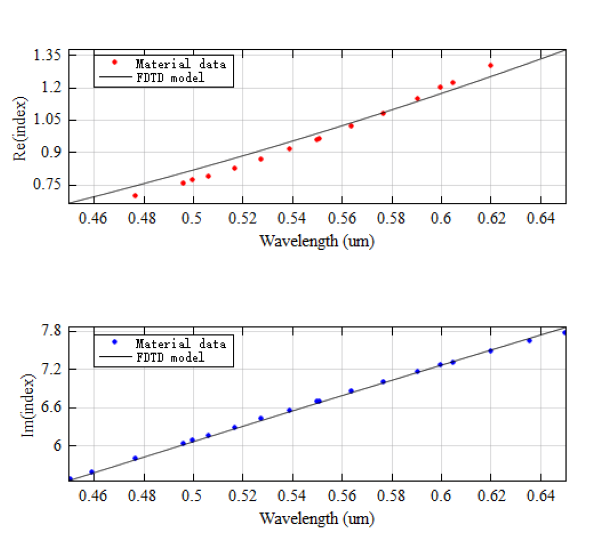
光栅材料来自内置材料库Al (Aluminium) - Palik,需要拟合,拟合波段为 ,拟合结果如下图所示。
仿真结果
结果表明,WGP 对于 TM 波(S-polarization, S-Pol)的反射率 极高( 90 % ),而 TE 波(P-polarization, P-Pol)则主要被透射(超过 75 % )。通过扫描不同光栅间距(pitch)下的透射/反射率,结果表明:在 450 nm 的波长下,使用 100 nm 间距的 WGP 可以实现极高的偏振消光比(超过 40000 ),与参考文献一致。
TE 和 TM 偏振的反射、透射率
打开附件工程,运行 sweep 中的T_TEM扫描。扫描完成之后,运行 TEM_RT_sweep.msf 文件,绘制 TE 和 TM 偏振的反射、透射率图。
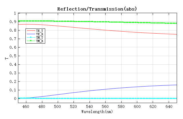
当光源以 TE 波入射时,超过 75 % 的入射光被透射;相反地,光以 TM 波入射时,几乎不存在透射, 90 % 的左右光被反射。以上表明了,WGP 对入射光具有偏振选择性。
PER 与光栅间距的关系
打开附件工程,运行 sweep 中的grating_pitch_sweep,然后运行 grating_pitch_sweep.msf,将 y 轴的尺度换成对数尺度,即可以得到下图。
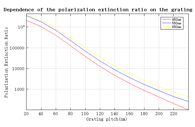
提取了 WGP 分别在波长 , 和 下,PER 与光栅间距的关系图,其结果与参考文献 Figure 2[1:1]一致。在 波长下,使用 间距的 WGP 可以实现高达 的 PER。
附录
S 偏振和 P 偏振
S 偏振和 P 偏振
在光入射到光学表面的问题中,讨论光的 S 偏振/P 偏振是非常常见的。然而,对于不同的文献,对此存在不同的定义,这可能会引起读者额外的理解困扰,相关阅读点击此处[1:2],两种定义方式的示意图如下图所示。
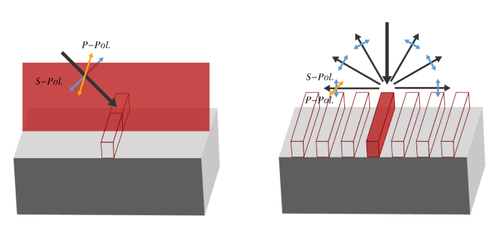
参考文献[1:3]遵循左图的规定(传统的定义方式)确定 S 偏振、P 偏振,本文与参考文献的定义方式保持一致。
与 TE、TM 的关系
TE、TM 分别表示横电(Transverse Electric)场、横磁(Transverse Magnetic)场。
特别的,当光线垂直入射时,使用传统的定义方式下,不难发现,S、P 偏振分别对应于二维仿真的 TM、TE 偏振。
偏振消光比
消光比
在电信领域,消光比(Extinction Ratio,ER)是两个光功率的比值,计算方式为:
其中, 、 分别为光源打开时的光功率和光源关闭时的光功率。
ER 是一个无量纲的物理量,通常会取 dB 表示,即:
偏振消光比
偏振消光比(Polatization Extinction Ratio,PER)是指两个正交偏振光功率之间的比值。一般而言,透射消光比的计算方式为:
和 分别为 S 偏振的光功率和 P 偏振的光功率,PER 的单位为 dB。
由于光源的总功率 一定,因此,
和 分别为 S 偏振的透射率和 P 偏振的透射率,PER 的单位为 dB。
由于 不能超过 100 %,增加 PER 最有效的方法是降低 。