返回应用案例
能激发塔姆等离激元的光栅
时域有限差分(FDTD)光栅等离激元
2024-03-01 14:01:42前言
在 2007 年,Kaliteevski 等人在金属和布拉格光栅之间成功激发塔姆等离激元(Tamm plasmon polaritons, TPPs)。这种新的光学效应不同于表面等离激元(surface plasmon polaritons, SPPs),塔姆等离激元的色散曲线位于光锥内,可以直接被激发,同时,其对光的入射角度没有要求并且 TE 或者 TM 偏振光都可以激发,而 SPPs 则仅支持 TM 偏振光激发。这些特性使得其在表面光增强、非线性光学以及激光等领域有着广阔的发展潜力,本案例将仿真研究该过程。
仿真设置
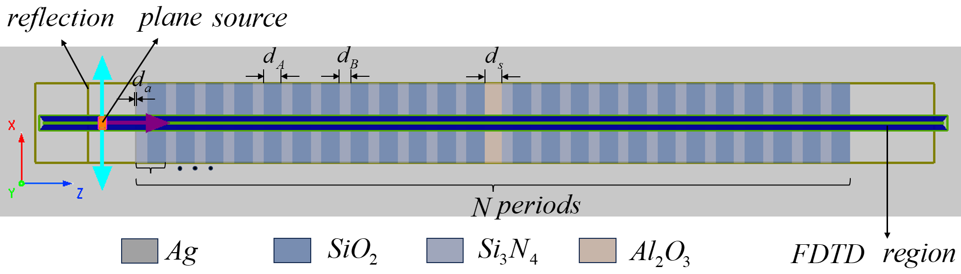
本案例使用 2D FDTD 仿真,构建如下图所示结构,在 x 方向上使用periodic边界条件,以节省计算时间。金属 层与布拉格光栅的相关参数参考文献[1],设置如下表所示
| 参数名称 | 符号 | 尺寸 |
|---|---|---|
材料
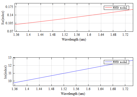
本案例当中 为 Drude 材料,其参数设置如下,拟合结果如下图所示。而布拉格光栅当中的 和 为普通的介电材料,其相对折射率分别为 1.45 和 2.2[1:1],缺陷层 的相对折射率为 1.76。
| 参数名称 | 符号 | 尺寸 |
|---|---|---|
| Permittivity | ||
| Drude pole frequency | ||
| Inverse of the pole relaxation time |
仿真结果
在布拉格光栅当中引入 1 层 作为缺陷时,会在原本的禁带内形成超窄带滤波器,此时反射光谱结果如下图所示

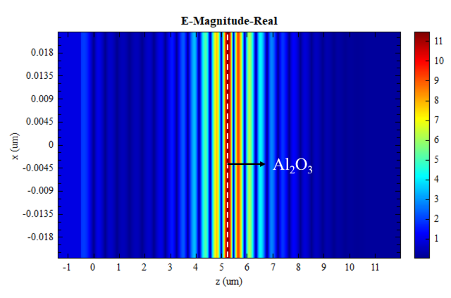
此时在 波段下的电场如下图所示,可以观察到在 处产生了共振
而不引入 缺陷时,其反射光谱如下图所示

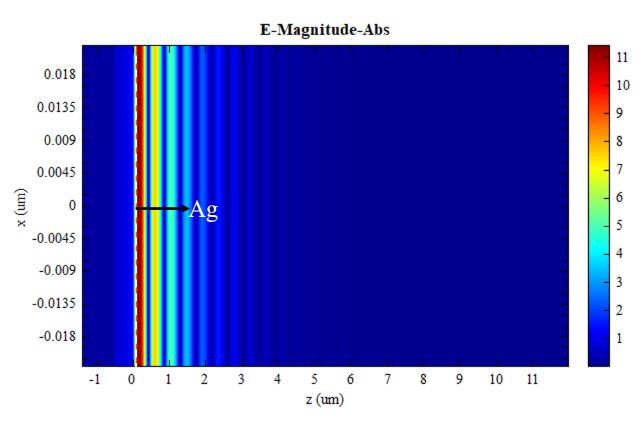
此时在 波段下的电场如下图所示,可以观察到光完全被布拉格光栅层吸收了
参数分析
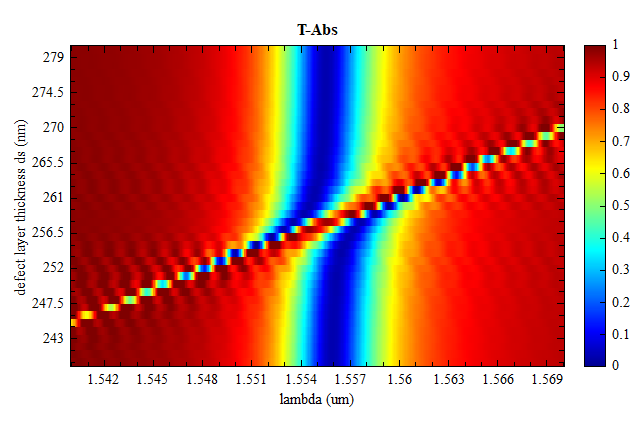
打开工程运行sweep_ds参数扫描,可以得到缺陷 的宽度对反射光谱的影响,如下图所示,随着缺陷的宽度增加,其新产生的共振峰的中心波长红移,结果与文献[1:2]当中Fig.3一致。