平面太阳能电池的光学仿真
前言
太阳能是清洁能源,因此太阳能的光电应用是近年来最具活力的研究领域之一。太阳能电池就是将太阳能转换为电能的器件,即太阳光照射到具有光伏效应的半导体材料时,产生电子-空穴对(光生载流子),在电池的两端引出电极就能产生电流。本案例中,我们使用 FDTD 模拟太阳光( )照射到平板硅基太阳能电池后的能量吸收,从而计算光子的生成率及对应的光电流。
仿真设置
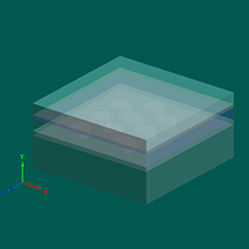
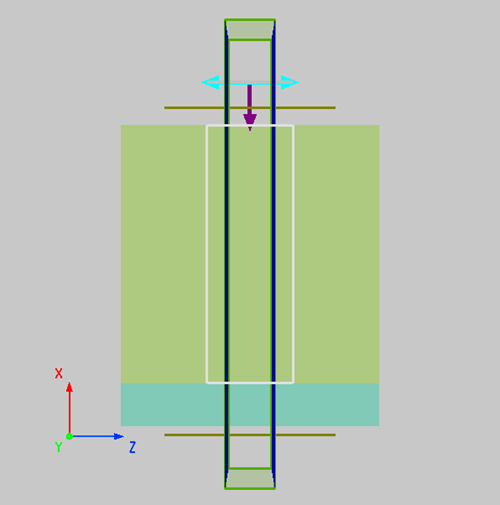
本案例使用平面波模拟太阳光照射硅基太阳能电池结构,在 Z 方向上使用Periodic周期性边界条件,这样可以只通过一个周期的仿真得到在该方向上无限周期的仿真结果。
材料设置
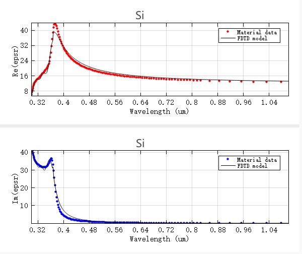
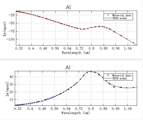
本案例中,硅、铝材料的介电常数能够大大地影响器件的光吸收,故在进行模拟仿真之前,需要查看材料在仿真波段内拟合的模型与数据点(Sampled data)的拟合误差。当拟合误差低于默认值(默认是 RMSE=0.1),拟合模型满足仿真需求;反之,请调整拟合误差和多项式最大的系数,重新拟合。下图展示了本案例中软件自动拟合的符合误差要求的结果。
仿真结果
太阳光的吸收与透射
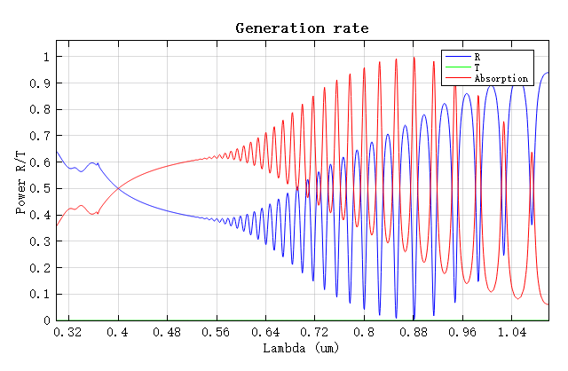
根据电池硅板顶部和底部的FDFP监视器中得到的 T 数据,可以绘制出太阳能电池的透射率、硅板的光吸收率和反射率,如下图。如图所示,整个电池的透射率为零,这是由于铝电极的全反射造成。反射率的波纹是由法布里-珀罗效应造成的。
光子生成率以及短路电流
如果将吸收的光能除以每个光子的能量,就是单位体积内吸收的光子数,再对其在频率(波长)上进行积分(如下式),即可得到太阳能电池中不同位置的光子生成率。
其中 为介电常数。
假设每个吸收的光子都能激发出一个电子-空穴对,即可产生光电流。电流的计算公式如下:
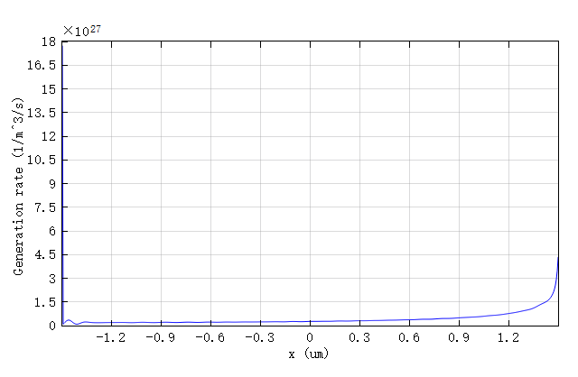
上式通过光子生成率计算出短路电流,而电流积分可以求出太阳能电池板的总短路电流,进而求出太阳能电池板短路电流的电流密度,计算结果约为 。由于本案例中在 Z 方向上没有变化,因此我们可以仅沿 X 轴观察光子生成率的变化规律(见下图):
光能量吸收效率的优化(减小反射)
考虑该器件在工作时,硅板表面会反射掉大量的太阳光,为了改善这一问题,我们选用 0.07um 厚度的 材料(n=2.05)覆盖在硅板表面充当防反射层(AR)。我们需要在软件中将 AR 结构改为 Enable 状态并重新运行仿真。
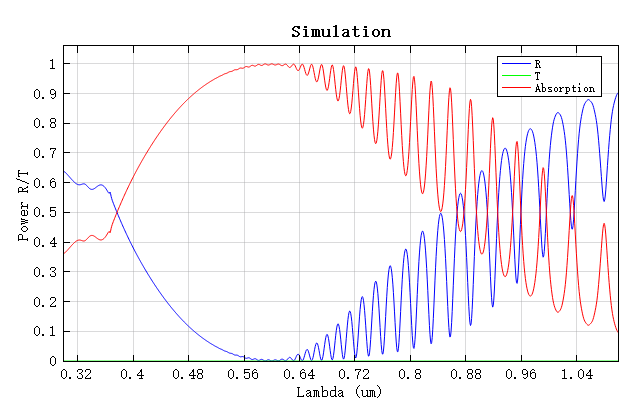
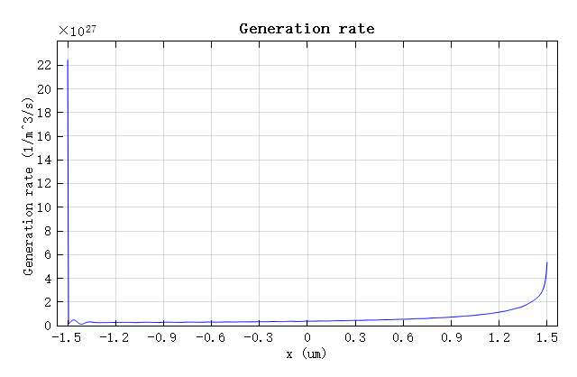
由仿真数据计算出的吸收率如上第一张图,X 方向上的生成率如上第二张图,计算出的光电流约为 ,这充分表明增加防反射层后,光电流明显增大。
附录
由于仿真中使用的平面波功率与太阳光功率不同,因此在计算光子生成率时需要按照平面波光源与太阳光的功率之比归一化成太阳光下的生成率。附件中提供的Solar.matmatlab 数据文件为太阳功率谱,单位为 Watts/meter^2/meter。这些数据来源于National Renewable Energy Laboratory(NREL) 美国国家可再生能源实验室 提供的太阳光标准总光谱辐照度分布ASTM G-173-03
相关视频