光子晶体布拉格光纤
前言
布拉格光纤是一种空芯光纤。这种光纤可以将光限制在空气纤芯中传播,从而避免了由于材料本征限制(吸收、色散、非线性、低损伤阈值等)而带来的问题,因此受到研究人员的广泛关注。本软件的 FDE 求解器可用于精确计算任意复杂结构的模式,包括光子晶体布拉格光纤。在本例中,我们使用 FDE 求解器计算了 Vienne 等人提出的光子晶体布拉格光纤的模式[1],并与 Uranus 等人对该光纤的分析结果对比[2]。
仿真设置
结构设置
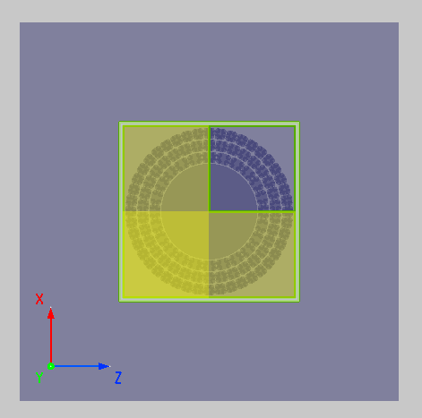
本例中使用的结构为 Vienne 等人提出的二氧化硅空气布拉格光纤。在光纤的中间有一个直径为 的复杂的微结构,此微结构的中心是一个直径为 的空气芯,空气芯的外围有三层二氧化硅环被 厚的空气环隔开,空气环中的支撑桥厚度大概为 。工程中的 PC Bragg Fiber 结构组中提供了该结构的绘制脚本,只需要按照要求在结构组中设置对应的Variables即可。
| Variable | Type | Value | Units |
|---|---|---|---|
| r_core | Length | 10 | microns(um) |
| t_annular | Length | 2.3 | microns(um) |
| t_ring | Length | 0.2 | microns(um) |
| t_bridge | Length | 0.045 | microns(um) |
| holes1 | Number | 24 | |
| holes2 | Number | 34 | |
| holes3 | Number | 44 | |
| y_span | Length | 0.3 | microns(um) |
其中,r_core 为空气芯的半径;t_annular 为空气环的厚度;t_ring 为空气芯的外沿到第一层二氧化硅环的距离;t_bridge 为支撑桥的厚度;holes1/2/3 分别为第 1/2/3 层空气孔的个数。
求解器设置
对称与反对称边界条件的使用需要结构与电磁场两者同时具备对称性。鉴于目标模式需要电场 Ez 在平行于 z 方向反对称,垂直于 z 方向对称,因此我们将 方向上的边界条件设置为Anti-Symmetric反对称边界条件。使用对称和反对称边界条件也可以在求解特征模式的仿真中消除不需要的、不具备对称性的模式从而减少仿真时间。在仿真中,我们使用的波长为 ,与文献[2:1]中使用的波长一致。从文献[2:2]的结果可以看出目标模式的有效折射率都在 0.998 附近,所以在解模时可以将Guess Value设置为 0.998,解模总数Total mode设置为 20,这样可以有效地减小解模范围,准确地找到需要的模式。
仿真结果
模式求解
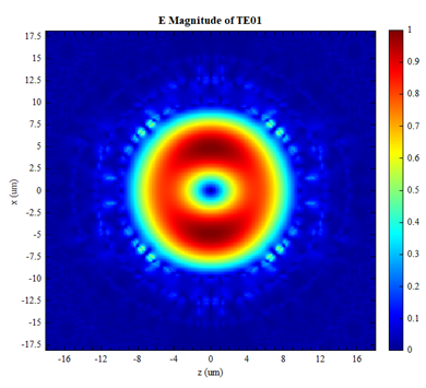
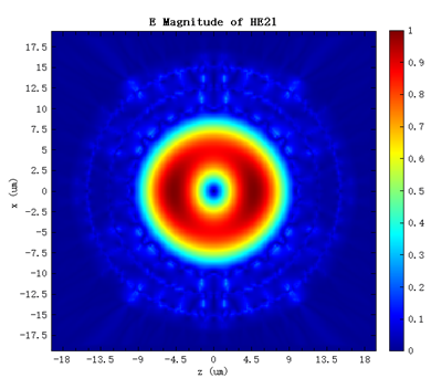
解模完成后,可以根据电磁场分布,在Modal List中识别出目标模式。其中“Mode#9”为 模,“Mode#10”为 模,其电场分布如下图:
下表为本软件计算出的 模和 模的有效折射率和损耗结果与文献中对应结果的对比。
| - | neff TE01 | neff HE21 | Loss TE01 | Loss HE21 |
|---|---|---|---|---|
| Simulation | 0.997929 | 0.997860 | 0.575939 | 3.36613 |
| Uranus et al. | 0.99791 | 0.99785 | 0.015 | 0.14 |
本软件计算出的有效折射率与文献中的结果非常接近。
收敛性测试
由于此类结构对网格的微小变化(以及实际加工缺陷)非常敏感,所以对仿真结果进行收敛性测试是必要的。我们将网格数从 200x200 到 800x800 不断细化,下图画出了 模和 模在不同网格数目下的有效折射率数值。
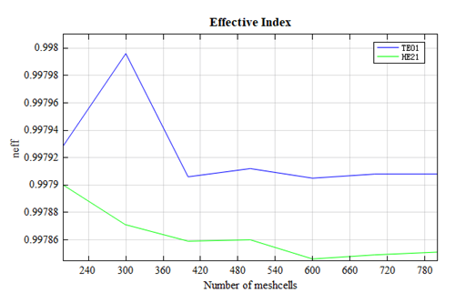
可以明显看出,随着网格数目的增加,对应模式的有效折射率逐渐收敛,在网格数为 800x800 的时候 模的有效折射率为 0.997908, 模的有效折射率为 0.997851,有效折射率结果正在向 Uranus 等人计算出的结果靠拢。
频率扫描
光纤的色散是指由于输入光信号的不同频率成分以不同速度传播,随着传播距离增加而引起的信号失真。我们对 模在频率从 240THz 到 280THz 的范围进行扫描,可以得到该模式的有效折射率 和色散 随波长的函数,如下图:
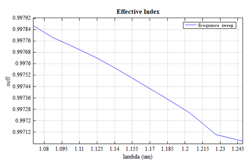
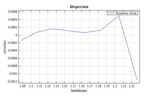
随着波长的增大,其有效折射率逐渐减小。从上图中可以看出,在某些波段下该光纤可以呈现出零色散或负色散的现象。所以该光纤是一种极低非线性,高损伤阈值的空心光纤,可以实现高速度、大容量、长距离的通信。
参考文献
G. Vienne, Y. Xu, C. Jakobsen, H.J. Deyerl, T.P. Hansen, B.H. Larsen et al., "First demonstration of air-silica Bragg fiber," Post Deadline Paper PDP25, Optical Fiber Conference 2004, Los Angeles, 22-27 Feb. 2004. ↩︎
H. Uranus and H. Hoekstra, "Modelling of microstructured waveguides using a finite-element-based vectorial mode solver with transparent boundary conditions," Opt. Express 12, 2795-2809 (2004) ↩︎ ↩︎ ↩︎