基于PB相位的超透镜
前言
传统的曲面光学透镜对光线的调控依赖于沿着光路的相位积累,因此会受到自然材料折射率的限制。为了修正各种图像像差,通常需要多个透镜组合。然而多个光学透镜的组合会占用大量的空间,使得光学系统难以小型化。而超透镜通过电介质表面上的人造亚波长单元的排列组合来操纵入射光,使光束弯曲。只需要一个超透镜,就能实现与需要多个光学透镜的设备同样的性能。与传统光学透镜相比,超透镜体积小、重量轻、成本低、成像好以及更易集成等优点,为紧凑集成的光学系统提供了新的解决方案。本案例基于 夏习成和姚赞[1] 的研究,介绍了如何使用 FDTD 进行超透镜的仿真,帮助读者实现光学系统的微型化。
仿真设置
模型构建
本案例使用的超透镜结构如上图,上层为玻璃基底,下层为 40 厚的金膜,在金膜的下表面有一个 10 孔径的光阑。金膜上有许多长方形的刻蚀孔。这些刻蚀孔的长宽分别为 , ,每一个刻蚀孔具有不同的旋转角度,为平面波引入相应的相移,最终将其调制成为球面波。为了将平面波调制成球面波,超透镜表面所需的相位分布为:
根据 PB 相位理论,当圆偏振光正入射时,透射出的交叉圆偏振光将会带有 的附加相位,其中 为矩形刻蚀孔单元的旋转角度。因此超透镜上每个刻蚀孔所需的旋转角度可以用其相对于透镜中心的坐标来表示:
工程的 etch 结构组中包含了构建这些刻蚀孔的脚本,您只需按照设计要求在结构组中设置对应的Variables即可。
由于刻蚀孔与金膜重合,所以在创建刻蚀孔结构时需要将折射率设置为 1,并且将Mesh order也设置为 1。关于Mesh Order的具体细节请参考Mesh order。
光源设置
大多数超透镜都是基于线偏振光进行的设计,而本案例使用的 PB 相位是 Pancharatnam 和 Berry 发现的一种对于圆偏振光的几何相位关系,当圆偏振光入射到结构上时,会产生与入射光相反旋向的交叉圆偏振光,通过适当的结构设计可以达到旋转光轴的效果,光轴与坐标轴的夹角发生改变,即可调控交叉圆偏振光的相位。
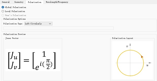
在本案例中,添加了一个平面光源位于结构的下方,沿着 Z 轴正向入射。本软件内置了多种光源偏振类型,在光源属性窗口的Polarization选项卡中可以方便的选择光源的偏振方式,这里选择 Left Cirularly 左旋圆偏振,如下图。
仿真结果
单个周期仿真
附件中的 Unit_cell.mpps 工程为超透镜单个周期的仿真工程,工程中包含了两个设置好的参数扫描,分别为 Phase_sweep 和 PCR_sweep 。其中 Phase_sweep 对刻蚀孔的旋转角度从 进行扫描,研究透射光场的相位变化。 PCR_sweep 则对入射光的波长从 进行扫描,研究不同波长入射时的偏振转化率。
运行参数扫描后可以得到,左旋偏振光入射时,右旋出射光的相位随刻蚀孔的旋转角的分布图如下。
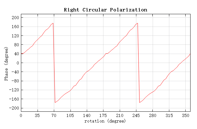
从图中可以看出,随着刻蚀孔的旋转,右旋出射光的相位呈现出明显的周期性变化,符合 PB 相位理论。
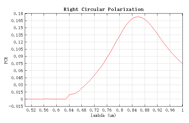
偏振转化率随波长的变化如下图,在波长 处得到最大的偏振转化率 ,与参考文献中的结果相差不到 。
全透镜仿真
附件中的 FullLens.mpps 工程为全透镜仿真工程,它的设计波长为 ,焦距 。仿真结束后,通过附件中的 FullLens.msf 脚本文件可以得到焦点附近的电场矢量图,您需要点击矢量图 figure 窗口中的设置,并按照如下设置才能得到与本文一致的图片。
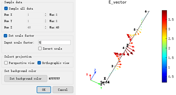
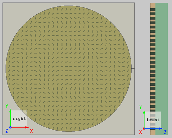
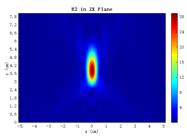
可以看到,此处的光线为右旋圆偏振,与入射的左旋圆偏振不同,说明该超透镜符合 PB 相位理论。光源经过透镜后的传播电场强度分布,如下图。可以看出,光源经过超透镜后成功会聚,焦点位于 处,与设计焦距相差 。
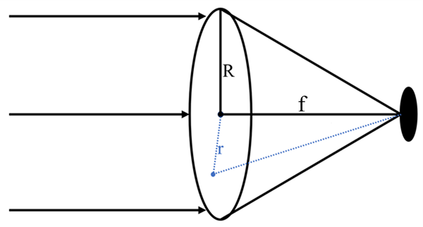
为了验证聚焦能量光斑与设计焦点是否一致,使用焦平面处焦斑的半宽高(FWHM)来表征光斑聚焦质量。其中 FWHM 的理论计算公式为:
式中, 为设计波长,数值孔径 ,其中 为介质折射率,空气中近似为 1, 为孔径角,通过理论计算得到 。
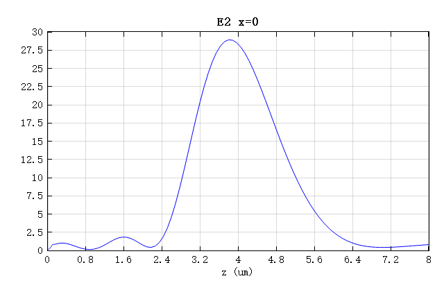
焦点处的电场强度分布如下图,可以计算出 ,与理论计算值基本一致。
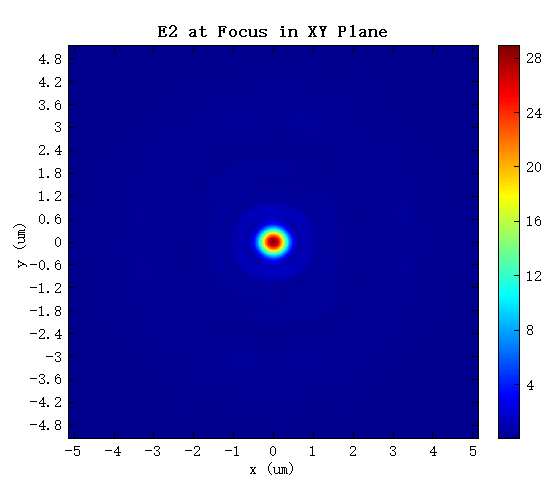
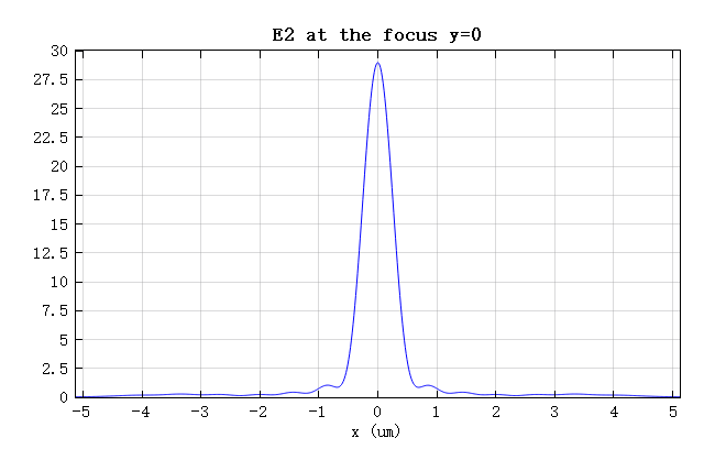
脚本同时还计算了该透镜的聚焦效率:焦平面内,以焦斑中心为圆点,3 倍半高宽为直径的圆内的透射功率与透过光阑的总功率之比,为 。仿真结果验证了理论与设计的正确性。
参考文献
Xicheng Xia, Zan Yao. Design of Plasma Metalens Based on PB Phase[J]. New technologies and new processes, 2020, (08): 46-48. ↩︎
相关视频
.jpg)