偏振分束的聚焦光栅耦合器
前言
随着 SOI 平台在集成光学领域的广泛应用,光栅耦合器凭借其易加工、易对准和易集成等优势,已成为硅基集成光路中至关重要的耦合器件。光纤中光的偏振态通常难以确定,而光栅耦合器对光的偏振十分敏感,对于不同偏振态的光,耦合效率差别很大。因此,近年来如何解决光纤与光波导的耦合问题已成为一个重要研究课题。偏振分束的光栅耦合器能够同时实现偏振分束和光的高效耦合两大功能,它采用垂直光栅耦合的方式,可以直接集成在 SOI 平台上,是该问题的最佳解决方案之一。
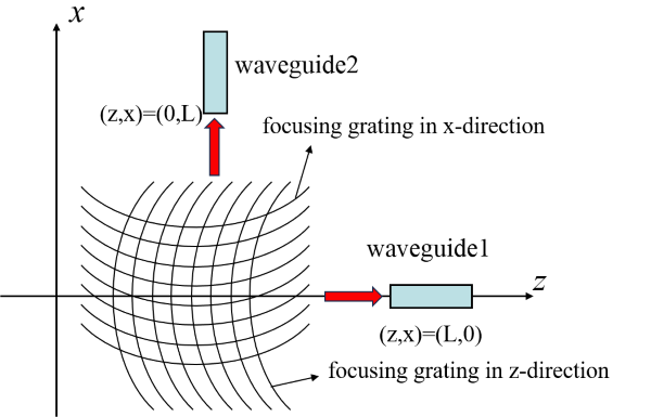
根据 Frederik 等人[1]的工作,本案例构建一个二维偏振分束的聚焦光栅耦合器。标准的二维偏振分束的聚焦光栅耦合器可以近似为两个一维的互相垂直的聚焦光栅耦合器叠加。光纤入射方向与光栅耦合器所在平面垂直,入射光经过光栅耦合器的偏振选择输出并聚焦到两个不同的输出波导端口中,如下图所示。
仿真设置
模型简介
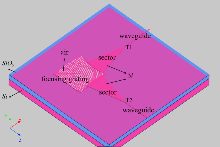
本案例使用 3D FDTD 仿真,构建仿真模型如下图所示。在器件与波导之间增加扇形结构可以有效减少耦合损耗。此时整个光栅耦合器放置在 SOI 平台上,SOI 为三层结构,最底层为 ,中间层为 ,上层放置 光波导器件。本案例当中的光栅耦合器为 衬底上刻蚀的一个个空气孔,其圆孔坐标即为两个一维聚焦光栅线的交点,其相关参数见参考文献[1:1],设置如下
| 参数名称 | 尺寸 |
|---|---|
| Waveguide Length | |
| Waveguide Depth | |
| Hole Depth | |
| Hole Radius | |
| L |
光源设置
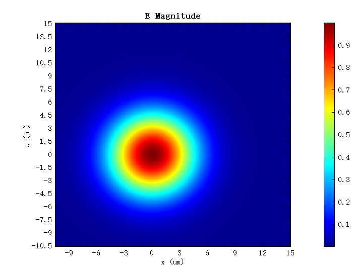
本案例当中使用高斯光源来模拟光纤当中的基模,为避免反射,将光源倾斜,此时高斯光源的束腰半径以及倾斜角等设置如下,其光源电场如下图所示
| 参数名称 | 尺寸 |
|---|---|
| Waist Width | |
| Angle Theta | |
| Angle Phi | |
| Linearly Polarization |
仿真结果
打开附件工程运行结束后,在FDTD monitor当中,在 1.5 波段下可以观察到光被均分到两个输出端口当中。

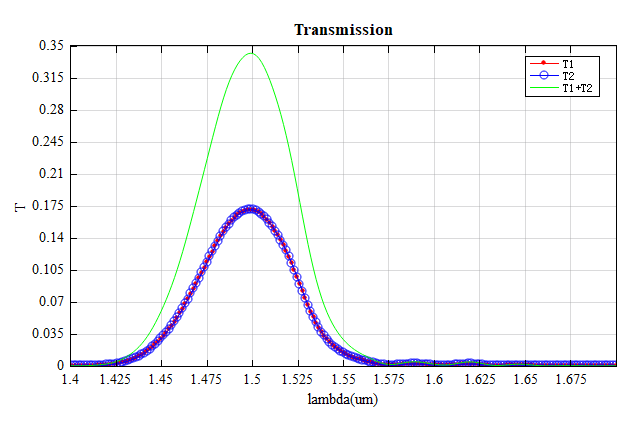
此时运行脚本focusing_grating_plot即可得到如下结果,从图中可以看到到两个输出端口的透射率相同,且 T1+T2 达到 0.34 以上。
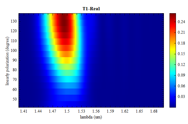
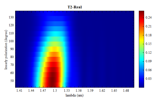
参数分析
运行参数扫描,在结果中可以观察到两个端口的透射率随光源线偏振角变化的趋势。随着线偏振角度从 45 度旋转到 135 度时,光也从一个输出端口转移到另一个输出端口。