基于FDTD的布拉格光栅
前言
布拉格光栅是一种结构的有效折射率存在周期性变化的光学器件。波导布拉格光栅可以近似一种一维光子晶体结构,通过周期性折射率调制,实现对波长的选择。通常利用这种特性将其制作成各种光学滤波片等。在本案例中,根据 wang 等人的工作可以探究在硅波导布拉格光栅当中,侧壁条纹的几何参数(如深度或者错位)对布拉格光栅性能的影响。
仿真设置
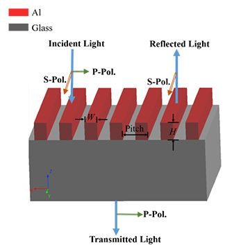
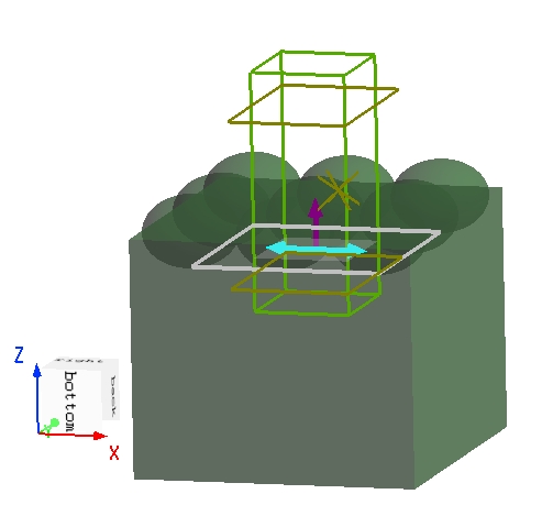
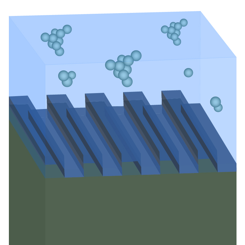
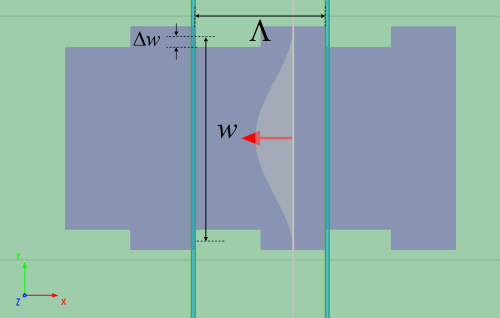
在本案例中,使用 3D FDTD 进行仿真,布拉格光栅是由硅材料组成的光栅器件放置在绝缘硅基平面上组成,其结构详见下图。在 x 方向上设置Bloch边界条件,仿真单个光栅周期,用来模拟无限周期的光栅。图中的结构参数,设置如下,其中 为布拉格光栅单个周期的单元长度, 为条纹平均宽度, 为光栅刻痕的深度。
| 参数名称 | 尺寸 |
|---|---|
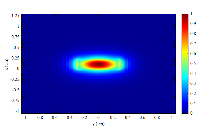
本案例当中光源使用模式光源,其基模 TE0 的场图如下。
材料设置
-
衬底
本案例中,衬底材料来自软件的内置材料库
SiO2(Glass) - Palik, 波长范围在 ~ ,材料的拟合结果如下图所示,在该波段下 的折射率实部和虚部分别为 和 。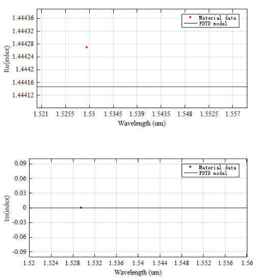
-
光栅
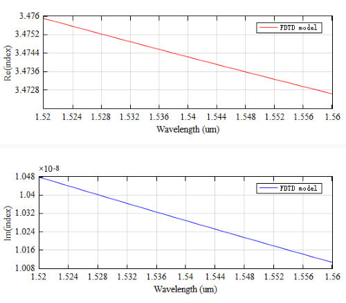
光栅材料为 Lorentz 模型建立的 Si 材料,关于 Lorentz 模型的具体细节请参考Drude_Debye_Lorentz。
本案例中, , , , ,此时 材料的折射率实部和虚部如下图所示:
仿真结果
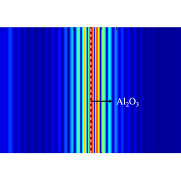
本案例中bandstructure可以计算布拉格光栅的光谱。运行结束后,该分析组会得到光栅在波矢 时的光谱。打开附录工程文件,直接运行,在bandstructure结果中,即可得到刻痕深度为 时,布拉格光栅的能带光谱,如下图所示
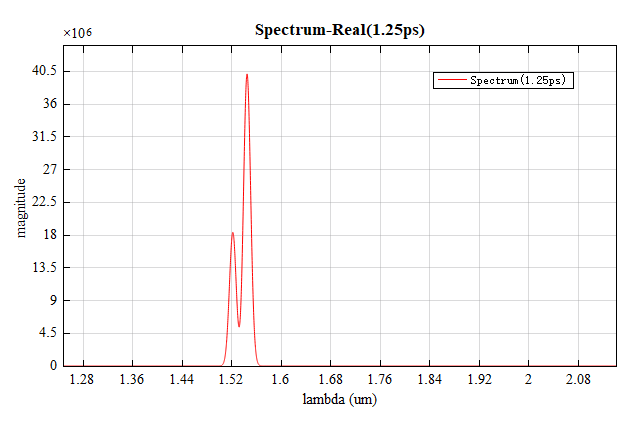
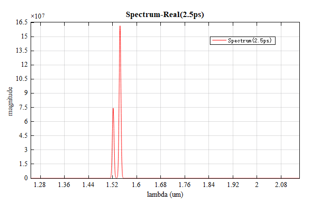
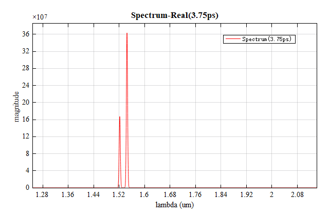
值得注意的是,光谱中共振峰的宽度与计算时间密切相关。计算时间越长,谐振越强,其峰值越尖。对于侧壁刻痕较浅的光栅结构,需要增加计算时间以区分光谱当中不同的共振峰。本案例工程当中初始时间设置为 。逐渐增加计算时间会使得共振峰的宽度减小,如下图所示,上图计算时间为 ,下图为 。
参数分析
从上面光谱中的两个共振峰的波长,可以计算得到带隙的大小(带宽)。进一步的,我们可以利用带隙的大小来分析光栅的性能。光栅与光栅中光学模式的相互作用,通常由耦合系数 来描述,表达式如下:
其中 为光栅的耦合系数, 为带宽, 为中心波长, 为中心波长处的群折射率。
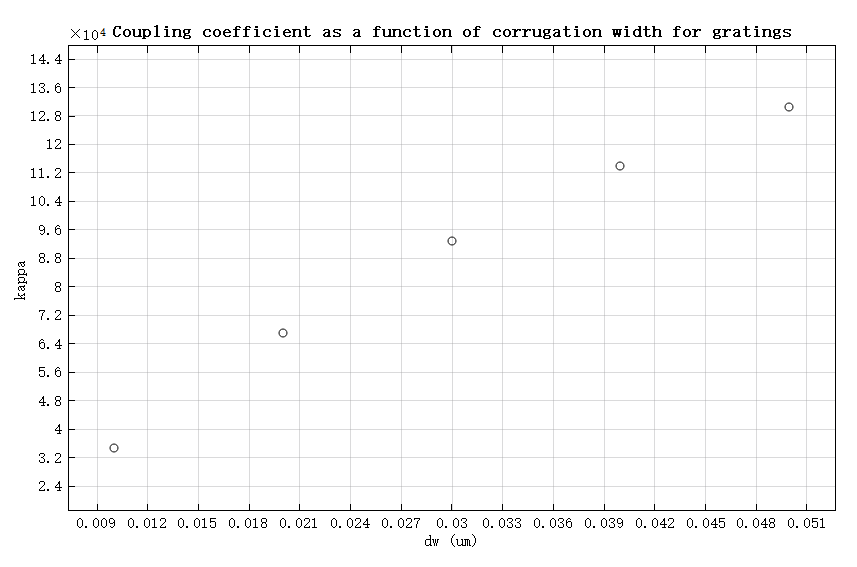
刻痕深度对光栅性能的影响
设置 从 增长到 进行扫描,可以观察到光栅刻痕的深度对光栅性能(耦合系数 )的影响。打开本案例附录工程,运行参数扫描后,将扫描结果当中的 绘制成散点图,即可得到光栅性能随光栅刻痕深度的变化趋势,如下图所示,与参考文献[1]Figure7 十分接近。
参考文献
X. Wang, et al., "Precise control of the coupling coefficient through destructive interference in silicon waveguide Bragg gratings", Opt. Lett. 39, 5519-5522 (2014). ↩︎