体心立方晶格和面心立方晶格能带结构
前言
体心立方晶格(Body Center Cubic Lattice, BCC)和面心立方晶格(Face Center Cubic Lattice, FCC)是 3D 光子晶体结构的两种常见的类型。本案例构建了体心立方晶格和面心立方晶格光子晶体模型,使用 FDTD 求解器分析其能带结构。
仿真设置
模型简介
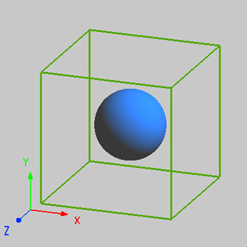
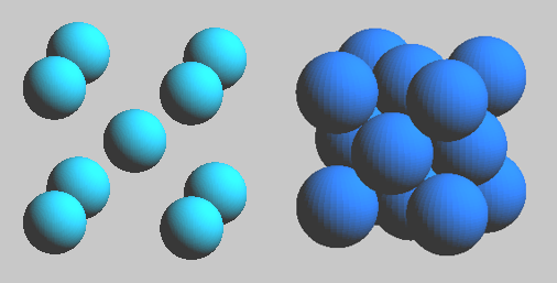
本案例使用 FDTD 求解器分析由均匀介质球按 FCC 和 BCC 两种晶格结构排列组成的光子晶体的能带结构。这两种晶格结构均属于立方晶系,但是它们的最小周期结构单元并非矩形结构,不符合 FDTD 矩形网格算法。因此,与3D 立方晶格能带结构的仿真设置有所不同,需要针对晶格类型对仿真对象做出特殊设置。
模型构建
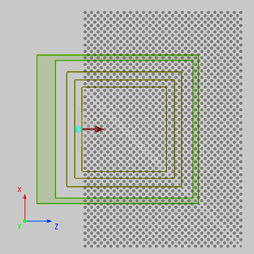
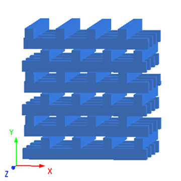
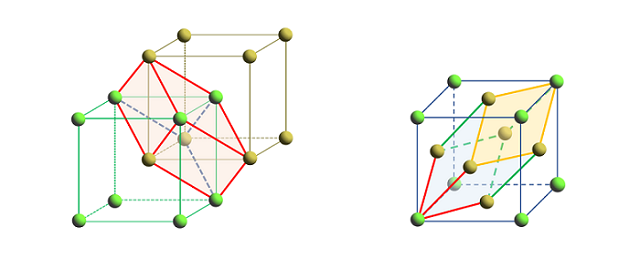
本案例中光子晶体模型构建和仿真设置与案例2D 正方晶格能带结构相似,在此不再重复,请下载附件工程文件查看案例模型的详细信息。BCC 与 FCC 晶格同属立方晶系,它们的晶胞形状都是立方体,符合 FDTD 对矩形仿真区域的基本要求。所以将仿真区域设置为与最简晶胞结构空间范围保持一致,区域边界设置为 Bloch 周期性边界条件。如下图中展示了 BCC 与 FCC 晶格中的原胞结构。与三角晶格相似,明显看出其最小周期结构为非矩形结构。在仿真区域中会包含多个初基原胞结构,其中 FCC 晶格光子晶体的仿真区域中至少要包含四个原胞单元。同样为了避免人工区域折叠的问题,要在每个原胞中设置相匹配的偶极子源,请参考案例2D 三角晶格能带结构获取更多相关信息。此外,在对 FCC 晶格仿真区域生成网格时,要保证网格单元关于中心坐标轴呈均匀对称分布,并且每个轴向的网格单元数能被 4 整除。从而确保每个球体结构区域的网格剖分方式相同,实现仿真区域中结构分布的周期性。详见附件中对应的仿真模型。
仿真结果
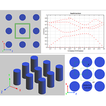
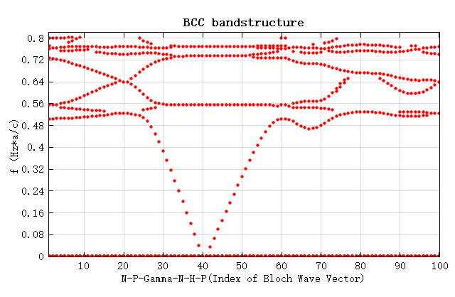
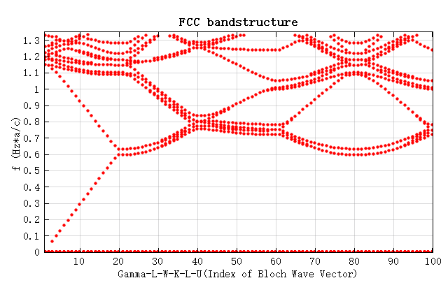
附件为 BCC 与 FCC 晶格光子晶体模型的工程文件。分别下载并打开工程文件,运行完成所有的参数扫描后,运行对应的脚本文件获取扫描结果并绘制能带结构图,如图所示。
相关视频
.jpg)